%\htmladdnormallink{href="http://blah.blah/blah"}{see blah}
%\htmladdimg}{blah.gif}
%\begin{rawhtml}
%\end{rawhtml}.
%\begin{htmlonly}
%\end{htmlonly} - Latex stuff
%\begin{latexonly}
%\end{latexonly}
%% The first argument is HTML text which will become ``hyperized''
%% (underlined).
%% The second and third arguments are text which will appear only in the paper
%% version (DVI file), enclosing the fourth argument which is a reference to a label.
%%
%%e.g. \hyperref{using the tracer}{using the tracer (see Section}{)}{trace}
%% where there is a corresponding \label{trace}
\documentstyle[twoside]{article}
\setlength{\textwidth}{ 6.1in}
\setlength{\oddsidemargin}{0.35in}
\setlength{\evensidemargin}{0.05in}
\setlength{\parindent}{0em}
\setlength{\parskip}{2ex}
\input {html.sty}
\def\RX#1#2{ \index{#1+}
{\large\bf{ #1 \hspace{3em} R$_1$,D$_2$(X$_2$,B$_2$) \hspace{5em} $[$RX$]$}}
\nopagebreak
\setlength{\unitlength}{1.0mm}
\begin{picture}(64,10)
\put(0,4){\framebox(64,6)}
\put(0,4){\makebox(16,6){#2}}
\put(16,4){\makebox(8,6){R$_1$}}
\put(24,4){\makebox(8,6){X$_2$}}
\put(32,4){\makebox(8,6){B$_2$}}
\put(40,4){\makebox(24,6){D$_2$}}
\put(16,4){\line(0,1){6}}
\put(24,4){\line(0,1){6}}
\put(32,4){\line(0,1){6}}
\put(40,4){\line(0,1){6}}
\footnotesize
\put(0,0){\makebox(16,6)[l]{31}}
\put(16,0){\makebox(8,6)[l]{23}}
\put(24,0){\makebox(8,6)[l]{19}}
\put(32,0){\makebox(8,6)[l]{15}}
\put(40,0){\makebox(24,6)[l]{11}}
\put(40,0){\makebox(24,6)[r]{0}}
\end{picture}
\nopagebreak
}
% eg. \RX{LH}{48}
\def\RXF#1#2{ % RX with MS field
{\large\bf{ #1 \hspace{3em} MS,D$_2$(X$_2$,B$_2$) \hspace{5em} $[$RX$]$}}
\nopagebreak \index{#1+}
\setlength{\unitlength}{1.0mm}
\begin{picture}(64,10)
\put(0,4){\framebox(64,6)}
\put(0,4){\makebox(16,6){#2}}
\put(16,4){\makebox(8,6){MS}}
\put(24,4){\makebox(8,6){X$_2$}}
\put(32,4){\makebox(8,6){B$_2$}}
\put(40,4){\makebox(24,6){D$_2$}}
\put(16,4){\line(0,1){6}}
\put(24,4){\line(0,1){6}}
\put(32,4){\line(0,1){6}}
\put(40,4){\line(0,1){6}}
\footnotesize
\put(0,0){\makebox(16,6)[l]{31}}
\put(16,0){\makebox(8,6)[l]{23}}
\put(24,0){\makebox(8,6)[l]{19}}
\put(32,0){\makebox(8,6)[l]{15}}
\put(40,0){\makebox(24,6)[l]{11}}
\put(40,0){\makebox(24,6)[r]{0}}
\end{picture}
\nopagebreak
}
% eg. \RXF{FW}{60}
\def\PLF#1#2{ % RX with MS field & PL
{\large\bf{ #1 \hspace{3em} MS,D$_2$(X$_2$,B$_2$) \hspace{5em} $[$PL$]$}}
\nopagebreak \index{#1+}
\setlength{\unitlength}{1.0mm}
\begin{picture}(64,10)
\put(0,4){\framebox(64,6)}
\put(0,4){\makebox(16,6){#2}}
\put(16,4){\makebox(8,6){MS}}
\put(24,4){\makebox(8,6){X$_2$}}
\put(32,4){\makebox(8,6){B$_2$}}
\put(40,4){\makebox(24,6){D$_2$}}
\put(16,4){\line(0,1){6}}
\put(24,4){\line(0,1){6}}
\put(32,4){\line(0,1){6}}
\put(40,4){\line(0,1){6}}
\footnotesize
\put(0,0){\makebox(16,6)[l]{31}}
\put(16,0){\makebox(8,6)[l]{23}}
\put(24,0){\makebox(8,6)[l]{19}}
\put(32,0){\makebox(8,6)[l]{15}}
\put(40,0){\makebox(24,6)[l]{11}}
\put(40,0){\makebox(24,6)[r]{0}}
\end{picture}
\nopagebreak
}
% eg. \PLF{FW}{60}
\def\RXm#1#2{ % RX with mask
{\large\bf{ #1 \hspace{3em} M$_1$,D$_2$(X$_2$,B$_2$) \hspace{5em} $[$RX$]$}}
\nopagebreak \index{#1+}
\setlength{\unitlength}{1.0mm}
\begin{picture}(64,10)
\put(0,4){\framebox(64,6)}
\put(0,4){\makebox(16,6){#2}}
\put(16,4){\makebox(8,6){M$_1$}}
\put(24,4){\makebox(8,6){X$_2$}}
\put(32,4){\makebox(8,6){B$_2$}}
\put(40,4){\makebox(24,6){D$_2$}}
\put(16,4){\line(0,1){6}}
\put(24,4){\line(0,1){6}}
\put(32,4){\line(0,1){6}}
\put(40,4){\line(0,1){6}}
\footnotesize
\put(0,0){\makebox(16,6)[l]{31}}
\put(16,0){\makebox(8,6)[l]{23}}
\put(24,0){\makebox(8,6)[l]{19}}
\put(32,0){\makebox(8,6)[l]{15}}
\put(40,0){\makebox(24,6)[l]{11}}
\put(40,0){\makebox(24,6)[r]{0}}
\end{picture}
\nopagebreak
}
% eg. \RXm{BC}{48}
\def\RXa#1#2{ % RX with R1 field blank
{\large\bf{ #1 \hspace{3em} D$_2$(X$_2$,B$_2$) \hspace{5em} $[$RX$]$}}
\nopagebreak \index{#1+}
\setlength{\unitlength}{1.0mm}
\begin{picture}(64,10)
\put(0,4){\framebox(64,6)}
\put(0,4){\makebox(16,6){#2}}
\put(24,4){\makebox(8,6){X$_2$}}
\put(32,4){\makebox(8,6){B$_2$}}
\put(40,4){\makebox(24,6){D$_2$}}
\put(16,4){\line(0,1){6}}
\put(16,8){\line(1,1){2}}
\put(16,4){\line(1,1){6}}
\put(20,4){\line(1,1){4}}
\put(24,4){\line(0,1){6}}
\put(32,4){\line(0,1){6}}
\put(40,4){\line(0,1){6}}
\footnotesize
\put(0,0){\makebox(16,6)[l]{31}}
\put(16,0){\makebox(8,6)[l]{23}}
\put(24,0){\makebox(8,6)[l]{19}}
\put(32,0){\makebox(8,6)[l]{15}}
\put(40,0){\makebox(24,6)[l]{11}}
\put(40,0){\makebox(24,6)[r]{0}}
\end{picture}
\nopagebreak
}
% eg. \RXa{RCSR0}{6F}
\def\PL#1#2{ % RX with R1 field blank
{\large\bf{ #1 \hspace{3em} D$_2$(X$_2$,B$_2$) \hspace{5em} $[$PL$]$}}
\nopagebreak \index{#1+}
\setlength{\unitlength}{1.0mm}
\begin{picture}(64,10)
\put(0,4){\framebox(64,6)}
\put(0,4){\makebox(16,6){#2}}
\put(24,4){\makebox(8,6){X$_2$}}
\put(32,4){\makebox(8,6){B$_2$}}
\put(40,4){\makebox(24,6){D$_2$}}
\put(16,4){\line(0,1){6}}
\put(16,8){\line(1,1){2}}
\put(16,4){\line(1,1){6}}
\put(20,4){\line(1,1){4}}
\put(24,4){\line(0,1){6}}
\put(32,4){\line(0,1){6}}
\put(40,4){\line(0,1){6}}
\footnotesize
\put(0,0){\makebox(16,6)[l]{31}}
\put(16,0){\makebox(8,6)[l]{23}}
\put(24,0){\makebox(8,6)[l]{19}}
\put(32,0){\makebox(8,6)[l]{15}}
\put(40,0){\makebox(24,6)[l]{11}}
\put(40,0){\makebox(24,6)[r]{0}}
\end{picture}
\nopagebreak
}
% eg. \PL{RCSR0}{6F}
\def\RR#1#2{
{\large\bf{ #1 \hspace{3em} R$_1$,R$_2$ \hspace{5em} $[$RR$]$}}
\nopagebreak \index{#1+}
\setlength{\unitlength}{1.0mm}
\begin{picture}(64,10)
\put(0,4){\framebox(64,6)}
\put(0,4){\makebox(16,6){#2}} % opcode
\put(16,4){\makebox(8,6){R$_1$}}
\put(24,4){\makebox(8,6){R$_2$}}
\put(16,4){\line(0,1){6}}
\put(24,4){\line(0,1){6}}
\put(32,4){\line(0,1){6}}
\put(32,8){\line(1,1){2}}
\put(32,4){\line(1,1){6}}
\put(36,4){\line(1,1){6}}
\put(40,4){\line(1,1){6}}
\put(44,4){\line(1,1){6}}
\put(48,4){\line(1,1){6}}
\put(52,4){\line(1,1){6}}
\put(56,4){\line(1,1){6}}
\put(60,4){\line(1,1){4}}
\footnotesize
\put(0,0){\makebox(16,6)[l]{31}}
\put(16,0){\makebox(8,6)[l]{23}}
\put(24,0){\makebox(8,6)[l]{19}}
\put(32,0){\makebox(8,6)[l]{15}}
\put(40,0){\makebox(24,6)[r]{0}}
\end{picture}
\nopagebreak
}
% eg. \RR{OR}{16}
\def\RRm#1#2{ % RR code with mask
{\large\bf{ #1 \hspace{3em} M$_1$,R$_2$ \hspace{5em} $[$RR$]$}}
\nopagebreak \index{#1+}
\setlength{\unitlength}{1.0mm}
\begin{picture}(64,10)
\put(0,4){\framebox(64,6)}
\put(0,4){\makebox(16,6){#2}} % opcode
\put(16,4){\makebox(8,6){M$_1$}}
\put(24,4){\makebox(8,6){R$_2$}}
\put(16,4){\line(0,1){6}}
\put(24,4){\line(0,1){6}}
\put(32,4){\line(0,1){6}}
\put(32,8){\line(1,1){2}}
\put(32,4){\line(1,1){6}}
\put(36,4){\line(1,1){6}}
\put(40,4){\line(1,1){6}}
\put(44,4){\line(1,1){6}}
\put(48,4){\line(1,1){6}}
\put(52,4){\line(1,1){6}}
\put(56,4){\line(1,1){6}}
\put(60,4){\line(1,1){4}}
\footnotesize
\put(0,0){\makebox(16,6)[l]{31}}
\put(16,0){\makebox(8,6)[l]{23}}
\put(24,0){\makebox(8,6)[l]{19}}
\put(32,0){\makebox(8,6)[l]{15}}
\put(40,0){\makebox(24,6)[r]{0}}
\end{picture}
\nopagebreak
}
% eg. \RRm{BC}{xx}
\def\RRa#1#2{
{\large\bf{ #1 \hspace{3em} R$_1$ \hspace{5em} $[$RR$]$}}
\nopagebreak \index{#1+}
\setlength{\unitlength}{1.0mm}
\begin{picture}(64,10)
\put(0,4){\framebox(64,6)}
\put(0,4){\makebox(16,6){#2}} % opcode
\put(16,4){\makebox(8,6){R$_1$}}
\put(16,4){\line(0,1){6}}
\put(24,4){\line(0,1){6}}
\put(24,8){\line(1,1){2}}
\put(24,4){\line(1,1){6}}
\put(28,4){\line(1,1){6}}
\put(32,4){\line(1,1){6}}
\put(36,4){\line(1,1){6}}
\put(40,4){\line(1,1){6}}
\put(44,4){\line(1,1){6}}
\put(48,4){\line(1,1){6}}
\put(52,4){\line(1,1){6}}
\put(56,4){\line(1,1){6}}
\put(60,4){\line(1,1){4}}
\footnotesize
\put(0,0){\makebox(16,6)[l]{31}}
\put(16,0){\makebox(8,6)[l]{23}}
\put(24,0){\makebox(8,6)[l]{19}}
\put(40,0){\makebox(24,6)[r]{0}}
\end{picture}
\nopagebreak
}
% eg. \RRa{SPM}{04}
\def\RS#1#2{
{\large\bf{ #1 \hspace{3em} R$_1$,R$_3$,D$_2$(B$_2$) \hspace{5em} $[$RS$]$}}
\nopagebreak \index{#1+}
\setlength{\unitlength}{1.0mm}
\begin{picture}(64,10)
\put(0,4){\framebox(64,6)}
\put(0,4){\makebox(16,6){#2}} % opcode
\put(16,4){\makebox(8,6){R$_1$}}
\put(24,4){\makebox(8,6){R$_3$}}
\put(32,4){\makebox(8,6){B$_2$}}
\put(40,4){\makebox(24,6){D$_2$}}
\put(16,4){\line(0,1){6}}
\put(24,4){\line(0,1){6}}
\put(32,4){\line(0,1){6}}
\put(40,4){\line(0,1){6}}
\footnotesize
\put(0,0){\makebox(16,6)[l]{31}}
\put(16,0){\makebox(8,6)[l]{23}}
\put(24,0){\makebox(8,6)[l]{19}}
\put(32,0){\makebox(8,6)[l]{15}}
\put(40,0){\makebox(24,6)[l]{11}}
\put(40,0){\makebox(24,6)[r]{0}}
\end{picture}
\nopagebreak
}
% eg. \RS{BXLE}{87} BXLE
\def\RSa#1#2{
{\large\bf{ #1 \hspace{3em} R$_1$,D$_2$(B$_2$) \hspace{5em} $[$RS$]$}}
\nopagebreak \index{#1+}
\setlength{\unitlength}{1.0mm}
\begin{picture}(64,10)
\put(0,4){\framebox(64,6)}
\put(0,4){\makebox(16,6){#2}} % opcode
\put(16,4){\makebox(8,6){R$_1$}}
\put(32,4){\makebox(8,6){B$_2$}}
\put(40,4){\makebox(24,6){D$_2$}}
\put(16,4){\line(0,1){6}}
\put(24,8){\line(1,1){2}}
\put(24,4){\line(1,1){6}}
\put(28,4){\line(1,1){4}}
\put(24,4){\line(0,1){6}}
\put(32,4){\line(0,1){6}}
\put(40,4){\line(0,1){6}}
\footnotesize
\put(0,0){\makebox(16,6)[l]{31}}
\put(16,0){\makebox(8,6)[l]{23}}
\put(24,0){\makebox(8,6)[l]{19}}
\put(32,0){\makebox(8,6)[l]{15}}
\put(40,0){\makebox(24,6)[l]{11}}
\put(40,0){\makebox(24,6)[r]{0}}
\end{picture}
\nopagebreak
}
% eg. \RSa{SLDL}{8D}
\def\RSb#1#2{
{\large\bf{ #1 \hspace{3em} \hspace{5em} $[$RS$]$}}
\nopagebreak \index{#1+}
\setlength{\unitlength}{1.0mm}
\begin{picture}(64,10)
\put(0,4){\framebox(64,6)}
\put(0,4){\makebox(16,6){#2}} % opcode
\put(16,4){\makebox(8,6){R$_1$}}
\put(16,4){\line(0,1){6}}
\put(24,4){\line(0,1){6}}
\put(24,8){\line(1,1){2}}
\put(24,4){\line(1,1){6}}
\put(28,4){\line(1,1){6}}
\put(32,4){\line(1,1){6}}
\put(36,4){\line(1,1){6}}
\put(40,4){\line(1,1){6}}
\put(44,4){\line(1,1){6}}
\put(48,4){\line(1,1){6}}
\put(52,4){\line(1,1){6}}
\put(56,4){\line(1,1){6}}
\put(60,4){\line(1,1){4}}
\footnotesize
\put(0,0){\makebox(16,6)[l]{31}}
\put(16,0){\makebox(8,6)[l]{23}}
\put(24,0){\makebox(8,6)[l]{19}}
\put(40,0){\makebox(24,6)[r]{0}}
\end{picture}
\nopagebreak
}
% eg. \RSb{SR32}{xx}
\def\SI#1#2{
{\large\bf{ #1 \hspace{3em} D$_1$(B$_1$),I$_2$ \hspace{5em} $[$SI$]$}}
\nopagebreak \index{#1+}
\setlength{\unitlength}{1.0mm}
\begin{picture}(64,10)
\put(0,4){\framebox(64,6)}
\put(0,4){\makebox(16,6){#2}}
\put(16,4){\makebox(16,6){I$_2$}}
\put(32,4){\makebox(8,6){B$_1$}}
\put(40,4){\makebox(24,6){D$_1$}}
\put(16,4){\line(0,1){6}}
\put(32,4){\line(0,1){6}}
\put(40,4){\line(0,1){6}}
\footnotesize
\put(0,0){\makebox(16,6)[l]{31}}
\put(24,0){\makebox(8,6)[l]{19}}
\put(32,0){\makebox(8,6)[l]{15}}
\put(40,0){\makebox(24,6)[l]{11}}
\put(40,0){\makebox(24,6)[r]{0}}
\end{picture}
\nopagebreak
}
% eg. \SI{MVI}{92}
\def\S#1#2{
{\large\bf{ #1 \hspace{3em} D$_2$(B$_2$) \hspace{5em} $[$S$]$}}
\nopagebreak \index{#1+}
\setlength{\unitlength}{1.0mm}
\begin{picture}(64,10)
\put(0,4){\framebox(64,6)}
\put(0,4){\makebox(16,6){#2}} % opcode
\put(32,4){\makebox(8,6){B$_2$}}
\put(40,4){\makebox(24,6){D$_2$}}
\put(16,4){\line(0,1){6}}
\put(16,8){\line(1,1){2}}
\put(16,4){\line(1,1){6}}
\put(20,4){\line(1,1){6}}
\put(24,4){\line(1,1){6}}
\put(28,4){\line(1,1){4}}
\put(32,4){\line(0,1){6}}
\put(40,4){\line(0,1){6}}
\footnotesize
\put(0,0){\makebox(16,6)[l]{31}}
\put(16,0){\makebox(8,6)[l]{23}}
\put(32,0){\makebox(8,6)[l]{15}}
\put(40,0){\makebox(24,6)[l]{11}}
\put(40,0){\makebox(24,6)[r]{0}}
\end{picture}
\nopagebreak
}
% eg. \S{SSM}{80}
%\input {defs.tex}
%\begin{latexonly}
\def\doublepagebreak{\if@twoside \ifodd
{\ifvmode \penalty -\@getpen{4}\else
\@bsphack\vadjust{\penalty -\@getpen{4}}\@esphack\fi}\fi\fi}
% eg. \doublepagebreak
%\end{latexonly}
\makeindex
\begin{document}
\begin{latexonly}
\begin{center}
{\Huge\bf SLAC Scanner Processor } \\
\vspace {0.3in}
{\Huge\bf SSP II} \\
\vspace {0.3in}
{\Huge\bf User Guide} \\
\vspace {2.0in}
{\Large\bf Hanoch Brafman, Jeff Olsen} \\
\vspace {0.06in}
{\Large\bf SLAC} \\
\vspace {0.06in}
{\Large\bf January 29, 1986} \\
\vspace {0.6in}
{\Large\bf Andrew Daviel} \\
\vspace {0.06in}
{\Large\bf TRIUMF} \\
\vspace {0.06in}
{\Large\bf November 1993}
\end{center}
\cleardoublepage
%\clearpage
\end{latexonly}
\begin{rawhtml}
SLAC Scanner Processor
SSP II
User Guide
Hanoch Brafman, Jeff Olsen
SLAC
January 29, 1986
Andrew Daviel
TRIUMF
February 1994
\end{rawhtml}
\pagebreak
\section{Table of Contents}
\tableofcontents
\pagebreak
\section{List of Tables}
\listoftables
\cleardoublepage
\section{Specifications}
%{\large\bf SSP II SPECIFICATIONS } \\
\subsection{ Package:}
Double width FASTBUS Module
\itemsep -1.0ex
\begin{itemize}
\item{CPU Board}
\item{Control Board}
\end{itemize}
\begin{rawhtml}
 \end{rawhtml}
\subsection{Front Panel}
\begin{itemize}
\item LED's indicating: \index{LED's}
\itemsep -1.0ex
\begin{description}
\item Slave on Cable - Yellow
\item Slave on Crate - Yellow
\item Master on Cable - Green
\item Master on Crate - Green
\item \hyperref{Internal SR}{}{}{csr0_SR} (DONE) - Red \index{SR} \index{DONE}
\item \hyperref{SR}{}{}{csr0_SR} on Cable - Red
\item \hyperref{SR}{}{}{csr0_SR} on Crate - Red
\item CPU running - Red
\item \hyperref{Single step/instruction}{}{}{csr0_SCYC} mode - Red \index{Single Step}
\item \hyperref{Power Fail}{}{}{csr0_PF} - Red (optional) \index{Power Fail}
\end{description}
\item Locking toggle switch for \hyperref{Reset}{}{}{csr0_Reset} \index{Reset}
\begin{description}
\item Resets the SSP only; Puts SSP to `sleep'
\end{description}
\item Push Button for Single step/instruction
\item LEMO (NIM) input for START \index{START}
\begin{description}
\item Starts SSP
\item Similar to \hyperref{TRIGGER bit in CSR\#0}{}{}{csr0_TRIG} \index{Trigger}
\end{description}
\item LEMO (TTL open collector) output for DONE
\begin{description}
\item Same as internal \hyperref{SR}{}{}{csr0_SR}
\end{description}
\item DIPswitch to select Cable Segment Geographic Address
\end{itemize} \index{Cable Segment}
\subsection{Memory and registers}
\begin{itemize}
\item \hyperref{CSR\#0}{}{}{s_CSR0}
\begin{description}
\item Read/Write from FASTBUS or the processor
\end{description}
\item \hyperref{CSR\#8}{}{}{s_CSR8} \index{CSR\#8}
\begin{description}
\item Write only from FASTBUS
\item Arbitration level common to both Crate and Cable segment
\end{description}
\item Program memory - 4K words or 64K words,
\hyperref{switchable}{}{}{EPM}
\begin{description} \index{Program Memory}
\item Read/Write from FASTBUS
\item Addressed in CSR space
\begin{description}
\item 40000000 - 4000FFFF
\end{description}
\end{description}
\item Data memory - 512K words, \hyperref{expandable}{}{}{Jumpers} to 2048K words
\begin{description} \index{Data Memory}
\item Read/Write from FASTBUS or the processor
\item Byte addressable from the processor
\item Addressed in DATA space
\begin{description}
\item 00000000 - 007FFFFC
\end{description}
\item Addressed in CSR space
\begin{description}
\item 80000000 - 807FFFFC
\end{description}
\end{description}
\end{itemize}
\subsection{Broadcast modes}\label{s_BRO}
\begin{itemize} \index{Broadcast+}
\item Case 1 (X'01') General - SSP attaches \index{Class N}
\item Case 2 (X'N5') \hyperref{Class N}{}{}{csr0_CLASS} - N is loaded into
\hyperref{CSR\#0}{}{}{s_CSR0}
\item Case 3a (X'19') SSP asserts TP on segment issuing the
broadcast if not busy \index{Busy}
\item Case 4 (X'0D') SSP asserts TP on segment issuing the
broadcast \index{TP}
\item Case 5 (X'1D') SSP asserts TP if it is asserting
\hyperref{SR}{}{}{csr0_SR} on segment
issuing the broadcast
\item Case 6 (X'2D') SSP asserts TP if
\hyperref{DONE}{}{}{csr0_SR} (SR flag) is set
\item Case 7 (X'\{8-F\}D') User may enable by burning a
\hyperref{PROM}{}{}{BCPROM}
\end{itemize} \index{SR} \index{DONE}
\subsection{Data Cycles}
\begin{itemize}
\item Secondary Address (Read/write)
\item Random Data (Read/Write)
\item Block Transfers - Handshake (Read/Write)
\begin{description} \index{Timing}
\item Timing -- Typical for Backplane
\item Slave:
\item Primary Address: AK UP response to AS UP - 40 ns
\item Random Data : DK UP response to DS UP - 215 ns read\\
DK UP response to DS UP - 140 ns write\\
DK DN response to DK DN - 50 ns
\item Block Transfer : DK T response to DS T - 120 ns
\item Master:
\item Random Data : DS DN response to DK UP - 140 ns read\\
DS DN response to DK DN - 50 ns write
\item Block Transfer : DS T response to DK T - 110 ns
\item Maximum Transfer rate (Slave response = 0 ns):
9 Mhz (110 ns/Word). \index{Block Transfer}
\end{description}
\end{itemize}
\subsection{SS Responses}\label{s_SS}
\begin{itemize}
\item SLAVE \index{SS+}
\begin{description}
\item SS = 0, Normal
\item SS = 1, SSP is busy
\item SS = 6, Addressing error
\end{description}
\end{itemize}
\begin{itemize}
\item MASTER
\begin{description}
\item Any SS other than 0 will generate an error
except where SS=2 terminates the \hyperref{block
transfer}{}{}{BLOCK}.
\end{description}
\end{itemize}
\subsection{ Parity:}
\begin{itemize} \index{Parity}
\item No parity checking is done
\end{itemize}
\subsection{ Reset Bus:}
\begin{itemize} \index{RB+}
\item Issued by another Master:
\begin{description}
\item Resets \hyperref{CSR\#0}{}{}{s_CSR0}.
The value of \hyperref{N}{}{}{csr0_CLASS} in CSR\#0 remains unchanged.
\item Puts SSP to `sleep'.
\item Leaves all memory and other registers unchanged.
\end{description}
\item Issued by the SSP:
\begin{description}
\item Ignored by the SSP
\item Segment determined by a \hyperref{bit in
CSR\#0}{}{}{csr0_RB}
\item Level or Pulse selected by \hyperref{jumper}{}{}{Jumpers}; if level,
Duration determined by setting
and resetting a \hyperref{bit in CSR\#0}{}{}{csr0_RB}
\end{description} \index{CSR\#0}
\item Issued through the scanner
\begin{description}
\item Ignored by the SSP
\item Segment determined by a bit in \hyperref{CSR\#0}{}{}{csr0_RB}
\item Duration determined by setting
and resetting a bit in CSR\#0
\end{description}
\end{itemize}
\subsection{ START:}
\begin{itemize} \index{START}
\item \hyperref{CSR\#0 Trigger}{}{}{csr0_TRIG}
\item TTL - LEMO
\end{itemize}
Multiple starts are ignored while the processor is running
\subsection{ CPU:}
\begin{itemize}
\item 32 Bit
\item Emulates IBM integer machine language instructions.
All instructions are 32 bits long.
\item Separated Data and Program memory.
\item Executes single or combined FASTBUS I/O operations.
\item Basic cycle time of 100 ns.
Narrowed to 80 during multiply, divide, and shifts.
\item Users I/O and Error handler starts at location 0
in Program memory.
Updated \hyperref{PSW}{}{}{s_PSW} in location 0 in data memory.
\hyperref{Memory Address register}{}{}{MAR} contents in location 4
in Data memory.
\item \hyperref{Interruptible}{}{}{INTRP} from either the Crate or Cable segment
at the end of an instruction or group of I/O instructions.
\hyperref{System mask}{}{}{SMSK} must be on.
\end{itemize}
\clearpage
\subsection{ SCANNER CSR's}
The SSP has only 2 CSR's, \hyperref{CSR\#0}{}{}{s_CSR0} and
\hyperref{CSR\#8}{}{}{s_CSR8}. CSR\#0 is a read/write
register, CSR\#8 is a write only register. \index{CSR\#8+}
\subsection{ CSR\#0:} The format of CSR\#0 is shown in Table
1.\label{s_CSR0}
%\end{document}
\begin{latexonly}
\begin{center}
\begin{tabular}{|llll|}
\multicolumn{4}{c}{\large Table 1: Format of CSR\#0} \\ \hline
\bf{Bit} & \bf{Hex} & \bf{Read} & \bf{Write} \\ \hline \index{CSR\#0+}
31 & 80000000 & & Disable EPM \\
30 & 40000000 & Bits 16-31 & Reset (disable Class N) \\
29 & 20000000 & Manufacturer's & \\
28 & 10000000 & I.D. & Enable EPM\\
\hline \index{EPM} \index{Class N}
27 & 08000000 & 0106 (no EPM) & Enable Class N response \\
26 & 04000000 & & Enable Time-outs \\
25 & 02000000 & 0107 (with EPM) & Disable CI SR \\
24 & 01000000 & & Enable CI Mastership \\
\hline \index{Timeout}
23 & 00800000 & & Disable GK up \\
22 & 00400000 & & Disable single cycle \\
21 & 00200000 & & Reset SR \\
20 & 00100000 & & Disable CR SR \\
\hline \index{SR}
19 & 00080000 & & Reset RB \\
18 & 00040000 & & Reset RUN, HALT \\
17 & 00020000 & & Enable CI RB \\
16 & 00010000 & EPM enabled & Enable writing of class \\
\hline
15 & & & \\
14 & 0000X000 & Bits 12-15 & Bits 12-15 \\
13 & & Class for case 2 & Set Class for case 2 \\
12 & & Broadcasts & Broadcasts \\
\hline \index{Broadcast}
11 & 00000800 & Class N enabled & Trigger \\
10 & 00000400 & Time-outs Disabled & Disable Time-outs \\
9 & 00000200 & CI SR Enabled & Enable CI SR \\
8 & 00000100 & CR Mastership Enabled & Enable CR Mastership \\
\hline \index{GK} \index{Single Step}
7 & 00000080 & Hold GK Enabled & Enable Hold GK \\
6 & 00000040 & Single cycle mode & Set single cycle mode \\
5 & 00000020 & SR set (DONE) & Set SR \\
4 & 00000010 & CR SR Enabled & Enable CR SR \\
\hline \index{DONE} \index{Trigger}
3 & 00000008 & Cable SR is set & Set RB \\
2 & 00000004 & RUN Bit Set & Set RUN Bit \\
1 & 00000002 & Crate SR is set & Enable CR RB \\
0 & 00000001 & Power fault & Set Soft Halt \\
\hline
\end{tabular}
CR - Crate segment, CI - Cable segment
\end{center}
\end{latexonly}
\begin{htmlonly}
\index{EPM} \index{Class N}
\index{DONE} \index{Trigger}
\index{SR}
\index{Broadcast}
\index{GK} \index{Single Step}
\begin{rawhtml}
\end{rawhtml}
         Table 1:  Format of CSR#0
{ \tt

Bit    Hex        Read               Write \\
31  80000000                         \hyperref{Disable EPM}{}{}{csr0_EPM}\\
30  40000000  Bits 16-31             \hyperref{Reset}{}{}{csr0_Reset} (disable Class N)\\
29  20000000  Manufacturer's\\
28  10000000  I.D.                   \hyperref{Enable EPM}{}{}{csr0_EPM}\\ \\
27  08000000  0106 (no EPM)          Enable \hyperref{Class N response}{}{}{csr0_CLASS}\\
26  04000000                         Enable \hyperref{Time-outs}{}{}{csr0_TO}\\
25  02000000  0107 (with EPM)        Disable CI \hyperref{SR}{}{}{csr0_SR}\\
24  01000000                         Enable CI \hyperref{Mastership}{}{}{csr0_Master}\\ \\
23  00800000                         Disable \hyperref{GK up}{}{}{csr0_GK}\\
22  00400000                         Disable \hyperref{single cycle}{}{}{csr0_SCYC}\\
21  00200000                         Reset \hyperref{SR}{}{}{csr0_SR}\\
20  00100000                         Disable CR \hyperref{SR}{}{}{csr0_SR}\\ \\
19  00080000                         Reset \hyperref{RB}{}{}{csr0_RB}\\
18  00040000                         Reset \hyperref{RUN}{}{}{csr0_RUN}, HALT\\
17  00020000                         Enable CI \hyperref{RB}{}{}{csr0_RB}\\
16  00010000  \hyperref{EPM}{}{}{csr0_EPM} enabled            Enable writing of \hyperref{class}{}{}{csr0_CLASS}\\ \\
15\\
14  0000X000  Bits 12-15             Bits 12-15\\
13            Class for case 2       Set \hyperref{Class}{}{}{csr0_CLASS} for case 2\\
12            Broadcasts             Broadcasts\\ \\

11  00000800  Class N enabled        \hyperref{Trigger}{}{}{csr0_TRIG}\\
10  00000400  Time-outs Disabled     Disable \hyperref{Time-outs}{}{}{csr0_TO}\\
09  00000200  CI \hyperref{SR}{}{}{csr0_SR} Enabled          Enable CI \hyperref{SR}{}{}{csr0_SR}\\
 08  00000100  CR Mastership Enabled  Enable CR \hyperref{Mastership}{}{}{csr0_Master}\\ \\
07  00000080  \hyperref{Hold GK}{}{}{csr0_GK}  Enabled       Enable \hyperref{Hold GK}{}{}{csr0_GK}\\
06  00000040  Single cycle mode      Set \hyperref{single cycle mode}{}{}{csr0_SCYC}\\
05  00000020  SR set (DONE)          Set \hyperref{SR}{}{}{csr0_SR}\\
04  00000010  CR \hyperref{SR}{}{}{csr0_SR} Enabled          Enable CR \hyperref{SR}{}{}{csr0_SR}\\ \\
03  00000008  Cable \hyperref{SR}{}{}{csr0_SR} is set        Set \hyperref{RB}{}{}{csr0_RB}\\
02  00000004  RUN Bit Set            Set \hyperref{RUN}{}{}{csr0_RUN} Bit\\
01  00000002  Crate \hyperref{SR}{}{}{csr0_SR} is set        Enable CR \hyperref{RB}{}{}{csr0_RB}\\
00  00000001  \hyperref{Power fault}{}{}{csr0_PF}            Set \hyperref{Soft Halt}{}{}{csr0_RUN}\\
} % \tt
           CR - Crate segment, CI - Cable segment
\begin{rawhtml}
\end{rawhtml}
\end{htmlonly}
%\subsection{CSR\#0 Bits}
\subsubsection{EPM}
\label{csr0_EPM}\index{EPM}
On reads, bits 16 through 31 indicate the manufacturer's I.D. For
the SSP, the I.D. is 0106(hex) with EPM disabled. For EPM enabled,
the I.D. is 0107.
\hyperref{Extended Program Memory}{}{}{EPM} (EPM) may be enabled or disabled by writing
bits 28 and 31. EPM is disabled at power-up.
\begin{latexonly} See page~{\pageref{EPM}} for a
more complete description.
\end{latexonly}
\subsubsection{Reset}
\label{csr0_Reset} \index{Class N}
Response to Class~N broadcasts may be enabled or disabled. In
accordance with the FASTBUS specification, Class N response is disabled at
power-up and by writing bit~30 (the Reset bit). Class~N response is enabled
by writing bit~27 (since CSR\#7 is not implemented). Class~N enabled is
indicated by bit~11.
\subsubsection{Bus Timeouts}
\label{csr0_TO} \index{Timeout}
Time-outs are disabled by setting bit~10. and enabled by setting
bit~26. With time-outs disabled, the SSP will wait forever to
get responses back from a slave. With time-outs enabled, the SSP
will wait 20.5 $\mu$s for responses from a slave. After this time
period, the I/O-Interrupt handler will be called.
\subsubsection{SR}
\label{csr0_SR} \index{SR}
The internal SR line is set true by setting bit~5. and set false
by setting bit~21. If the internal SR line is true, the SSP will
assert TP for broadcast case 5.
The internal SR line can be asserted on either the cable
segment or crate segment or both. Setting bit~9 enables the internal SR
onto the cable segment, bit~25 disables it. Setting bit~4 enables
the internal SR onto the crate segment, bit~20 disables it.
\subsubsection{Bus Mastership}
\label{csr0_Master} \index{Cable Segment}
The SSP can be a master on either the cable segment or the crate
segment. Setting bit~8 will enable mastership on the crate segment.
Setting bit~24 will enable mastership on the cable segment.
\subsubsection{Hold GK}
\label{csr0_GK } \index{GK+}
The Hold GK feature enables the SSP to maintain GK asserted after
dropping AS/AK lock. This allows the SSP to scan from module to
module without having to regain bus mastership. If the Hold GK
feature is disabled, the SSP will drop GK upon receiving AK.
Setting bit~7 will enable the Hold GK feature, bit~23 will disable
it.
\subsubsection{Single Cycle}
\label{csr0_SCYC} \index{Single Step+}
The SSP program can be stepped through by setting bit~6 and then
using the front panel button. This feature is useful for debugging
hardware. Setting bit~22 will disable the single step feature. A jumper on
the control board controls whether the SSP executes a single
clock cycle or a single instruction on each push of the front
panel button.
\subsubsection{Reset Bus (RB)}
\label{csr0_RB} \index{RB+}
Setting bit~3 will set the internal RB line true. Setting bit~19
will set the internal RB line false. Setting bit~1 will direct
the RB to the crate segment, bit~ 17 will direct the RB to the
cable segment. This allows the cable segment to issue a RB into
the crate segment through the SSP. Setting bits 1 and 3 from the
cable segment will set RB in the crate. Setting bit~19 will drop
the RB in the crate. A jumper on the control board controls whether
setting bit~3 generates a pulse on RB or a level.
\subsubsection{Run}
\label{csr0_RUN}
\index{RUN+}
Setting bit~2 will enable the SSP to RUN. The SSP must be
triggered by either setting bit~11, trigger bit, or a front panel
start. Setting bit~18 will halt the SSP.
\subsubsection{Class N Broadcast}
\label{csr0_CLASS}
\index{Broadcast}
The value of the class for case 2 broadcast is written into bits
12 through 15. This register is not of the J-K type. In order
to load the class register, bit~16 must also be set. If bit~16
is not set, bits 12 through 15 are not loaded into the class register.
Case~2 broadcast response is enabled by writing bit~27.
\subsubsection{Trigger}
\label{csr0_TRIG}
\index{Trigger+}
Bit~11 is the Trigger bit. This bit will start the SSP if the
RUN bit (bit~2) was also set.
\subsubsection{Power Fault} \index{Power Fail+} \label{csr0_PF}
Bit~0 indicates a power fault condition. Voltages on each fused
section of both the SSP CPU and Control boards are monitored and a power
fail signal is asserted if any voltage falls below tolerance. Indication is
made by LEDs fitted to each board, optionally by a front-panel LED, and by
setting bit~0. If a power fault exists on the CPU board the FASTBUS slave
interface will still function. However a fault on the Control board will
probably render the slave interface inoperative.
\subsection{ CSR\#8} \index{CSR\#8+} \index{Arbitration}\label{s_CSR8}
CSR\#8 is a write only register which contains
arbitration level and the assured access bit.
\clearpage
\subsection{ I/O INTERRUPT AND ERROR HANDLER} \index{Error Handler+}
\label{s_ERRHND}
The I/O-Error Handler is a program that is executed when the SSP
is externally interrupted or encounters an error. Hardware-wise,
entering the I/O-Error Handler does the following:
\begin{enumerate}
\item Stores the Processor Status Word (PSW) into DM~0. \index{PSW}
\item Stores the Memory Address Register (MAR) into DM~4. \index{MAR}
\item Sets the System Mask and Overflow Mask OFF;
Disables Interrupts \index{Interrupt}
\item Jumps to PM 0 and starts executing the I/O-Error Handler.
\end{enumerate}
It is up to the I/O-Error Handler to determine what action to
take in response to the I/O-Error. The reason that the I/O-Error
Handler was entered can be decoded from the PSW and the MAR.
\subsection{ I/O Interrupts:} In order for the SSP to be
interruptible, the System Mask must be ON. Turning ON the
System Mask is done by setting bit~15 ON in the Initial PSW (if
EPM is disabled) or by using the Set System \index{System Mask}
Mask (SSM) instruction. If the System Mask is ON, trying to
attach to the SSP from either the Crate or Cable Segment will
interrupt the SSP. If the SSP is executing a sequence of I/O
instructions, the interrupt will not be acknowledged until a
non-I/O instruction or an instruction having a Primary address is
executed. If the SSP is not executing I/O instructions, the
interrupt will not be acknowledged until the end of the current
instruction.
Bit~ 31 of the PSW indicates that the I/O-Error Handler
was entered because of an I/O Interrupt. It is the
responsibility of the I/O-Error Handler to put the SSP to `sleep'
by writing to CSR0 and resetting the RUN bit. \index{PSW}
If the System Mask is ON and a Master attempts to attach to
the SSP, the SSP will return AK and WT during the Primary Address
cycle. WT will be released only after the I/O-Error Handler has
reset the RUN bit in CSR0. \index{WT}
If the System Mask is OFF and a Master attempts to attach to
the SSP, the SSP will return AK during the Primary Address cycle.
The SSP will return an SS=1, BUSY, for any subsequent address or
data cycles. \index{Busy+} \index{SS}
To continue executing the program from the point it was
interrupted, DM~0 must be loaded with the correct PSW. This PSW is
either the same PSW that was loaded into DM~0 when the interrupt
occurred, or one less than it. The NPA Bit in the PSW indicates
whether to subtract 1 or not. If the NPA Bit is 1, subtract 1,
otherwise subtract 0. After the correct PSW is loaded into DM~0,
set the RUN Bit and the Start Bit in CSR\#0 to continue execution.
To start the SSP running in a different location than where
the interrupt occurred, load the desired PSW into DM~0. Then set
the RUN and Start Bit in CSR\#0 to start the SSP. \index{RUN}
\index{START}
\subsection{ ERRORS:} \label{s_ERRORS}
Besides handling I/O Interrupts, the I/O-Error Handler
must also handle the following error condition:
\begin{enumerate}
\item Unsupported Op-Code
\item Divide by Zero
\item Overflow, if the Overflow Mask is ON \index{Overflow}
\item An unexpected non-zero SS code \index{SS}
\item A word-count overflow during block transfers using the word
count as a guard. \index{Word Count}
\end{enumerate}
\clearpage
\subsection{ EXTENDED PROGRAM MEMORY } \label{EPM} \index{EPM+}
Extended Program Memory (EPM) refers to a PM size of 64kW instead of 4kW.
This is achieved by using a 16-bit PC instead of a 12-bit PC. This extended
PC is too large to be saved in the PSW, so two instructions must be used
instead of one. \index{PSW} \index{PC}
In order to remain compatible with existing SSP software, EPM is initially
disabled on power-up. When EPM is disabled, only the lower 4k words of
program memory may be accessed, and the Program Counter (PC) is 12 bits long.
When EPM is enabled, the full 64k words of program memory is available, and
the PC is 16 bits long.
Initial Program Load (IPL) loads the PC with the PM address found in Data
Memory address zero (DM~0), and also sets the system masks (LSMSK, LPMSK).
Programs compiled for EPM must have an initial \index{IPL}
DM~0 of 0080, not 8080, and the system mask must be set with an SSM
instruction if required. A DM~0 of 8080 would cause the SSP to start executing at
address 8080 in addition to setting the mask. \index{System Mask}
When EPM is enabled, the instructions \hyperref{BAL, BALR}{}{}{i_BAL},
\hyperref{BALR0}{}{}{i_BALR0} save a 16-bit PC
and do not save the program masks. \index{BAL} \index{BALR} \index{BALR0}
Thus the link address is saved in the register, but the original
values of the condition codes and system masks are lost. If these are
required, they must be explicitly saved beforehand using a
\hyperref{BALR0M}{}{}{i_BALR0M}
instruction. \index{BALR0M}
When EPM is enabled, the interrupt microcode (IOERR) clears the system
mask (disabling interrupts) and saves a 16-bit PC. The error handler code
must perform a BALR0M instruction to save the condition codes. The previous
value of the system mask is lost, but if a consistent procedure is used to
set and clear the mask then a copy may be kept in data memory. On exit from
the error handler, an \hyperref{LMSK}{}{}{i_LMSK} instruction should be executed to restore the
condition codes and masks, followed by an \hyperref{LPC}{}{}{i_LPC} instruction to restore the PC.
Executing an \hyperref{LPSW}{}{}{i_LPSW} instruction while EPM is enabled would cause
the upper PC bits to be set to the CC and masks values.
\index{LMSK} \index{LPSW}
With EPM enabled, a base register must be used (as in the IBM~370) to access
the upper 60kW of Program Memory.
\clearpage
\subsection{ PSW FORMAT}
The format of the PSW is shown in Table 2. \label{s_PSW}
\begin{latexonly}
\begin{center}
\begin{tabular}{|llll|}
\multicolumn{4}{c}{\large {Table 2: Format of the SSP PSW}} \\ \hline
{\bf Bit} & {\bf Hex} & {\bf Name} & {\bf Meaning } \\
\hline \index{PSW+}
31 & 80000000 & INTRP & I/O INTERRUPT \\
30 & 40000000 & EXCP & EXCEPTION \\
29 & 20000000 & T.O. & I/O TIME-OUT \\
28 & 10000000 & SS2 & SS2, SS1 and SS0 \\
\hline \index{Exception}
27 & 08000000 & SS1 & indicate the FASTBUS SS code \\
26 & 04000000 & SS0 & \\
25 & 02000000 & BRQ & BUS request by the SSP \\
24 & 01000000 & EG & Indicates a Primary Address cycle \\
\hline \index{SS} \index{EG}
23 & 00800000 & AS/AK & AS/AK lock was established \\
22 & 00400000 & MS1 & MS1 and MS0 indicate the FB MS code \\
21 & 00200000 & MS0 & \\
20 & 00100000 & RDOT & Indicates a FASTBUS Read cycle. \\
\hline \index{MS}
19 & 00080000 & WTOT & Indicates that SSP was issuing Wait \\
18 & 00040000 & EXCP2 & EXCP2 and EXCP1 \\
17 & 00020000 & EXCP1 & indicate the type of EXCEPTION \\
16 & 00010000 & /NPA & Next Prom Address \\
\hline \index{NPA} \index{System Mask}
15 & 00008000 & SMSK & System Mask \\
14 & 00004000 & OVMSK & Overflow Mask \\
13 & 00002000 & ECC2 & ECC2 and ECC1 \\
12 & 00001000 & ECC1 & Encoded Condition Codes \\
\hline \index{Condition Code} \index{Overflow}
11 & & & If EPM is disabled, bits 15:12 \\
10 & & & are the values of masks and \\
9 & & & condition codes. \\
8 & & &\\
\hline
7 & 00000XXX & & If EPM is enabled, bits 15:12\\
6 & & & indicate the upper 4 bits of the PC\\
5 & & &\\
4 & & &\\
\hline
3 & & & Bits 11:0 indicate the PC\\
2 & & & at the time the\\
1 & & & I/O-Error handler was entered\\
0 & & &\\
\hline
\end{tabular}
\end{center}
\end{latexonly}
\begin{htmlonly}
\index{PSW+}
\index{Exception}
\index{NPA} \index{System Mask}
\index{SS} \index{EG}
\index{MS}
\index{Condition Code} \index{Overflow}
\begin{rawhtml}\end{rawhtml}
{\large {Table 2: Format of the SSP PSW}}\\
{\bf Bit} {\bf Hex} {\bf Name} {\bf Meaning }\\
31 80000000 INTRP \hyperref{I/O INTERRUPT}{}{}{INTRP}\\
30 40000000 EXCP \hyperref{EXCEPTION}{}{}{EXCP}\\
29 20000000 T.O. \hyperref{I/O TIME-OUT}{}{}{IOTO}\\
28 10000000 SS2 SS2, SS1 and SS0\\
27 08000000 SS1 indicate the \hyperref{FASTBUS SS code}{}{}{FBSS}\\
26 04000000 SS0\\
25 02000000 BRQ \hyperref{BUS request}{}{}{BRQ} by the SSP\\
24 01000000 EG \hyperref{Indicates a Primary Address}{}{}{FBEG} cycle\\
23 00800000 AS/AK \hyperref{AS/AK lock}{}{}{ASAK} was established\\
22 00400000 MS1 \hyperref{MS1 and MS0}{}{}{FBMS} indicate the FB MS code\\
21 00200000 MS0\\
20 00100000 RDOT Indicates a FASTBUS \hyperref{Read cycle}{}{}{RDOT}.\\
19 00080000 WTOT Indicates that SSP was issuing \hyperref{Wait}{}{}{WTOT}\\
18 00040000 EXCP2 EXCP2 and EXCP1\\
17 00020000 EXCP1 indicate the type of \hyperref{EXCEPTION}{}{}{EXCP}\\
16 00010000 /NPA \hyperref{Next Prom Address}{}{}{NPA}\\
15 00008000 SMSK \hyperref{System Mask}{}{}{SMSK}\\
14 00004000 OVMSK \hyperref{Overflow Mask}{}{}{OVMSK}\\
13 00002000 ECC2 ECC2 and ECC1\\
12 00001000 ECC1 \hyperref{Encoded Condition Codes}{}{}{ECC}\\
11 If \hyperref{EPM}{}{}{EPM} is disabled, bits 15:12\\
10 are the values of masks and\\
09 condition codes.\\
08\\
07 00000XXX If \hyperref{EPM}{}{}{EPM} is enabled, bits 15:12\\
06 indicate the upper 4 bits of the PC\\
05\\
04\\
03 Bits 11:0 indicate the PC\\
02 at the time the\\
01 \hyperref{I/O-Error handler}{}{}{ERHND} was entered\\
00\\
\begin{rawhtml}\end{rawhtml}
\end{htmlonly}
\subsubsection{ INTRP} \index{Interrupt} \label{INTRP}
Indicates that the I/O-Error handler was entered due to an I/O
interrupt.
\subsubsection{ EXCP} \index{Exception} \label{EXCP}
Indicates that the
I/O-Error handler was entered due to an EXCEPTION. EXCP2 and
EXCP1 (bits 18 and 17 of the PSW), and A17 (the MSB of the MAR, for
a given memory size), indicate the type of exception. \index{MAR}
The exception is determined from Table 3.
\begin{latexonly}
\begin{center}
\begin{tabular}{|lll|}
\multicolumn{3}{c}{\large {Table 3: Exceptions}}\\
\hline \index{Exception+}
EXCP2 & EXCP1 & Explanation\\
\hline
0 & 0 & Divide by zero if A17 is low,\\
& & Data Memory wrap-around if A17 is high\\
\hline
0 & 1 & Arithmetic Overflow\\
\hline \index{Overflow}
1 & 0 & Unsupported Opcode\\
\hline \index{Word Count}
1 & 1 & FASTBUS block transfer terminated due to\\
& & a word count overflow\\
\hline
\end{tabular}
\end{center}
\end{latexonly}
\begin{htmlonly}
{\large {Table 3: Exceptions}}\\
\index{Word Count}
\index{Exception+}
\index{Overflow}
\begin{verbatim}
EXCP2 EXCP1 Explanation
0 0 Divide by zero if A17 is low,
Data Memory wrap-around if A17 is high
0 1 Arithmetic Overflow
1 0 Unsupported Opcode
1 1 FASTBUS block transfer terminated due to
a word count overflow
\end{verbatim}
\end{htmlonly}
\subsubsection{ T.O.} \label{IOTO}
Indicates that the I/O-Error handler was entered due to a FASTBUS
Time-Out. \index{Timeout}
\subsubsection{ SS2-SS0} \label{FBSS}
Indicate the SS code at the time the I/O-Error Handler was
entered. \index{SS}
\subsubsection{ BRQ} \label{BRQ}
Indicates that the SSP was requesting the BUS, Crate or Cable.
\subsubsection{ EG} \label{FBEG}
Internal Enable Geographic, indicates that a Primary Address was
in progress.
\subsubsection{ AS/AK} \label{ASAK}
Indicates that the AS/AK lock was established when the I/O-Error
Handler was entered.
\subsubsection{ MS1-MS0} \label{FBMS}
Indicate the MS code at the time when the I/O-Error Handler was
entered.
\subsubsection{ RDOT} \label{RDOT}
Indicates that the SSP was issuing a RD to the BUS, Crate or
Cable.
\subsubsection{ WTOT} \index{WT} \label{WTOT}
Indicates that the SSP was issuing a WT to the BUS, Crate or
Cable.
\subsubsection{ EXCP2, EXCP1}
Indicates the type of exception encountered as described above.
\subsubsection{ NPA} \index{NPA+} \index{PSW}
This bit is used to determine whether or not to subtract 1 from
the PSW to resume execution of the MAIN program. If this bit is
HIGH, the PSW must be decremented by 1. If this bit is LOW, the
PSW is left alone.
\subsubsection{ SMSK} \index{System Mask} \index{Interrupt}
\label{SMSK}
System Mask bit. If this bit is ON, I/O Interrupts are enabled.
If this bit is OFF, the SSP will not acknowledge I/O Interrupts.
\subsubsection{ OVMSK} \index{Overflow+} \label{OVMSK}
Overflow Mask bit. If this bit is ON, an Overflow will generate
an Exception. If this bit is OFF, an Overflow will be ignored.
\subsubsection{ ECC2, ECC1} \index{Condition Code} \label{ECC}
Encoded condition code bits. Program Counter Bits 11~-~0
indicate the P.C. at the time the I/O-Error Handler was entered.
Because of the instruction pipelining in the SSP, this P.C. may point to
the instruction that would have been executed had an error not been
encountered, or 1 past it. The NPA bit is used to determine whether to
subtract one or not. \index{NPA}
\clearpage
\subsection{ IBM Instructions:}
The SSP emulates IBM~370 integer machine language instructions as well
as several SSP specific instructions.
Table 4 lists the IBM instructions and Table 5
lists the SSP specific instructions.
\begin{latexonly}
\begin{center}
\begin{tabular}{|llll|}
\multicolumn{4}{c}{\large {Table 4: IBM Instructions}}\\
\hline
{\bf Op} & & &\\
{\bf Code} & {\bf Mnemonic} & {\bf Name} & {\bf Type}\\
\hline
5 & BALR & BRANCH AND LINK & RR\\
6 & BCTR & BRANCH ON COUNT & RR\\
7 & BCR & BRANCH ON CONDITION & RR\\
1A & AR & ADD & RR\\
1B & SR & SUBTRACT & RR\\
1C & MR & MULTIPLY & RR\\
1D & DR & DIVIDE & RR\\
1E & ALR & ADD LOGICAL & RR\\
1F & SLR & SUBTRACT LOGICAL & RR\\
10 & LPR & LOAD POSITIVE & RR\\
11 & LNR & LOAD NEGATIVE & RR\\
12 & LTR & LOAD AND TEST & RR\\
13 & LCR & LOAD COMPLEMENT & RR\\
14 & NR & AND & RR\\
15 & CLR & COMPARE LOGICAL & RR\\
16 & OR & OR & RR\\
17 & XR & EXCLUSIVE OR & RR\\
18 & LR & LOAD & RR\\
19 & CR & COMPARE & RR\\
4A & AH & ADD HALFWORD & RX\\
4B & SH & SUBTRACT HALFWORD & RX\\
4C & MH & MULTIPLY HALFWORD & RX\\
40 & STH & STORE HALFWORD & RX\\
41 & LA & LOAD ADDRESS & RX\\
42 & STC & STORE CHARACTER & RX\\
43 & IC & INSERT CHARACTER & RX\\
45 & BAL & BRANCH AND LINK & RX\\
46 & BCT & BRANCH ON COUNT & RX\\
47 & BC & BRANCH ON CONDITION & RX\\
48 & LH & LOAD HALFWORD & RX\\
49 & CH & COMPARE HALFWORD & RX\\
\hline
\end{tabular}
\end{center}
\begin{center}
\begin{tabular}{|llll|}
\multicolumn{4}{c}{\large {Table 4: IBM Instructions (continued)}}\\
\hline
{\bf Op} & & &\\
{\bf Code} & {\bf Mnemonic} & {\bf Name} & {\bf Type}\\
\hline
5A & A & ADD & RX\\
5B & S & SUBTRACT & RX\\
5C & M & MULTIPLY & RX\\
5D & D & DIVIDE & RX\\
5E & AL & ADD LOGICAL & RX\\
5F & SL & SUBTRACT LOGICAL & RX\\
50 & ST & STORE & RX\\
54 & N & AND & RX\\
55 & CL & COMPARE LOGICAL & RX\\
56 & O & OR & RX\\
57 & X & EXCLUSIVE OR & RX\\
58 & L & LOAD & RX\\
59 & C & COMPARE & RX\\
8A & SRA & SHIFT RIGHT SINGLE & RS\\
8B & SLA & SHIFT LEFT SINGLE & RS\\
8C & SRDL & SHIFT RIGHT DOUBLE LOGICAL& RS\\
8D & SLDL & SHIFT LEFT DOUBLE LOGICAL & RS\\
8E & SRDA & SHIFT RIGHT DOUBLE & RS\\
8F & SLDA & SHIFT LEFT DOUBLE & RS\\
86 & BXH & BRANCH ON INDEX HIGH & RS\\
87 & BXLE & BRANCH ON INDEX LOW OR EQUAL & RS\\
88 & SRL & SHIFT RIGHT SINGLE LOGICAL & RS\\
89 & SLL & SHIFT LEFT SINGLE LOGICAL & RS\\
90 & STM & STORE MULTIPLE & RS\\
91 & TM & TEST UNDER MASK & SI\\
92 & MVI & MOVE IMMEDIATE & SI\\
94 & NI & AND IMMEDIATE & SI\\
95 & CLI & COMPARE LOGICAL IMMEDIATE & SI\\
96 & OI & OR IMMEDIATE & SI\\
97 & XI & EXCLUSIVE OR IMMEDIATE & SI\\
98 & LM & LOAD MULTIPLE & RS\\
\hline
\end{tabular}
\end{center}
\end{latexonly}
\begin{htmlonly}
{\large {Table 4: IBM Instructions }}\\
\begin{rawhtml}\end{rawhtml}
{\bf Op}\\
{\bf Code} {\bf Mnemonic} {\bf Name} {\bf Type}\\
\hline
5A \hyperref{A}{}{}{i_A} ADD RX\\
4A \hyperref{AH}{}{}{i_AH} ADD HALFWORD RX\\
5E \hyperref{AL}{}{}{i_AL} ADD LOGICAL RX\\
1E \hyperref{ALR}{}{}{i_ALR} ADD LOGICAL RR\\
1A \hyperref{AR}{}{}{i_AR} ADD RR\\
45 \hyperref{BAL}{}{}{i_BAL} BRANCH AND LINK RX\\
05 \hyperref{BALR}{}{}{i_BALR} BRANCH AND LINK RR\\
47 \hyperref{BC}{}{}{i_BC} BRANCH ON CONDITION RX\\
07 \hyperref{BCR}{}{}{i_BCR} BRANCH ON CONDITION RR\\
46 \hyperref{BCT}{}{}{i_BCT} BRANCH ON COUNT RX\\
06 \hyperref{BCTR}{}{}{i_BCTR} BRANCH ON COUNT RR\\
86 \hyperref{BXH}{}{}{i_BXH} BRANCH ON INDEX HIGH RS\\
87 \hyperref{BXLE}{}{}{i_BXLE} BRANCH ON INDEX LOW OR EQUAL RS\\
59 \hyperref{C}{}{}{i_C} COMPARE RX\\
49 \hyperref{CH}{}{}{i_CH} COMPARE HALFWORD RX\\
55 \hyperref{CL}{}{}{i_CL} COMPARE LOGICAL RX\\
95 \hyperref{CLI}{}{}{i_CLI} COMPARE LOGICAL IMMEDIATE SI\\
15 \hyperref{CLR}{}{}{i_CLR} COMPARE LOGICAL RR\\
19 \hyperref{CR}{}{}{i_CR} COMPARE RR\\
5D \hyperref{D}{}{}{i_D} DIVIDE RX\\
1D \hyperref{DR}{}{}{i_DR} DIVIDE RR\\
43 \hyperref{IC}{}{}{i_IC} INSERT CHARACTER RX\\
58 \hyperref{L}{}{}{i_L} LOAD RX\\
41 \hyperref{LA}{}{}{i_LA} LOAD ADDRESS RX\\
13 \hyperref{LCR}{}{}{i_LCR} LOAD COMPLEMENT RR\\
48 \hyperref{LH}{}{}{i_LH} LOAD HALFWORD RX\\
98 \hyperref{LM}{}{}{i_LM} LOAD MULTIPLE RS\\
11 \hyperref{LNR}{}{}{i_LNR} LOAD NEGATIVE RR\\
10 \hyperref{LPR}{}{}{i_LPR} LOAD POSITIVE RR\\
82 \hyperref{LPSW}{}{}{i_LPSW} LOAD PSW S\\
18 \hyperref{LR}{}{}{i_LR} LOAD RR\\
12 \hyperref{LTR}{}{}{i_LTR} LOAD AND TEST RR\\
5C \hyperref{M}{}{}{i_M} MULTIPLY RX\\
4C \hyperref{MH}{}{}{i_MH} MULTIPLY HALFWORD RX\\
1C \hyperref{MR}{}{}{i_MR} MULTIPLY RR\\
92 \hyperref{MVI}{}{}{i_MVI} MOVE IMMEDIATE SI\\
54 \hyperref{N}{}{}{i_N} AND RX\\
94 \hyperref{NI}{}{}{i_NI} AND IMMEDIATE SI\\
14 \hyperref{NR}{}{}{i_NR} AND RR\\
56 \hyperref{O}{}{}{i_O} OR RX\\
96 \hyperref{OI}{}{}{i_OI} OR IMMEDIATE SI\\
16 \hyperref{OR}{}{}{i_OR} OR RR\\
5B \hyperref{S}{}{}{i_S} SUBTRACT RX\\
4B \hyperref{SH}{}{}{i_SH} SUBTRACT HALFWORD RX\\
5F \hyperref{SL}{}{}{i_SL} SUBTRACT LOGICAL RX\\
8B \hyperref{SLA}{}{}{i_SLA} SHIFT LEFT SINGLE RS\\
8F \hyperref{SLDA}{}{}{i_SLDA} SHIFT LEFT DOUBLE RS\\
8D \hyperref{SLDL}{}{}{i_SLDL} SHIFT LEFT DOUBLE LOGICAL RS\\
89 \hyperref{SLL}{}{}{i_SLL} SHIFT LEFT SINGLE LOGICAL RS\\
1F \hyperref{SLR}{}{}{i_SLR} SUBTRACT LOGICAL RR\\
04 \hyperref{SPM}{}{}{i_SPM} SET PROGRAM MASK RR\\
1B \hyperref{SR}{}{}{i_SR} SUBTRACT RR\\
8A \hyperref{SRA}{}{}{i_SRA} SHIFT RIGHT SINGLE RS\\
8E \hyperref{SRDA}{}{}{i_SRDA} SHIFT RIGHT DOUBLE RS\\
8C \hyperref{SRDL}{}{}{i_SRDL} SHIFT RIGHT DOUBLE LOGICAL RS\\
88 \hyperref{SRL}{}{}{i_SRL} SHIFT RIGHT SINGLE LOGICAL RS\\
80 \hyperref{SSM}{}{}{i_SSM} SET SYSTEM MASK S\\
50 \hyperref{ST}{}{}{i_ST} STORE RX\\
42 \hyperref{STC}{}{}{i_STC} STORE CHARACTER RX\\
40 \hyperref{STH}{}{}{i_STH} STORE HALFWORD RX\\
90 \hyperref{STM}{}{}{i_STM} STORE MULTIPLE RS\\
91 \hyperref{TM}{}{}{i_TM} TEST UNDER MASK SI\\
57 \hyperref{X}{}{}{i_X} EXCLUSIVE OR RX\\
97 \hyperref{XI}{}{}{i_XI} EXCLUSIVE OR IMMEDIATE SI\\
17 \hyperref{XR}{}{}{i_XR} EXCLUSIVE OR RR\\
\begin{rawhtml}\end{rawhtml}
\end{htmlonly}
\subsection{ Program Execution}
Normally , operation of the CPU is controlled by instructions taken in
sequence. This sequence is governed by the program status word (PSW) ,
which \index{PSW}
contains the primary information required for proper program execution.
A
change in the sequential operation may be caused by branching, LOAD PSW,
interruptions, or manual intervention.
\subsection{ Instructions}
Each instruction consists of two major parts : (1) an operation code ,
which
specifies the operation to be performed, and (2) the designation of the
operands that participate.
{\bf Operands }\\
Operands can be grouped in three classes : operands located in
registers,
immediate operands, and operands in main storage. Operands may be either
explicitly or implicitly designated.
% Register operands can be located in general, floating-point, or control
%registers, with the type of register identified by the operation code.
Register operands are located in one of the general registers R0 - R15.
The
register containing the operand is specified by identifying the
register in a
four-bit field, called the R field, in the instruction. For some
instructions an
operand is
located in an implicitly designated register, the register being
implied by the
operation code.
Immediate operands are contained within the instruction, and the
eight-bit
field containing the immediate operand is called the I field.
Operands in main storage may either have an implied length, be
specified by a
bit mask, or, in other cases, be specified by a four-bit or eight-bit
length
specification, called the L field, in the instruction. The addresses of
operands in main storage are specified by means of a format that uses
the
contents of a general register as part of the address. This makes it
possible to:
\begin{itemize}
\item {Specify a complete address by using an abbreviated notation.}
\item
{ Perform address manipulation using instructions which employ general
registers for operands}
\item{ Modify addresses by program means without alteration of the
instruction stream.}
\item { Operate independently of the location of data areas by directly using
addresses received from other programs.}
\end{itemize}
The address used to refer to main storage either is contained in a
register
designated by the {\bf R} field in the instruction or is calculated from a
base
address,
index, and displacement, designated by the {\bf B}, {\bf X},
and {\bf D} fields. respectively, in the instruction.
For purposes of describing the execution of instructions, operands are
designated as first and second operands and. in some cases, third
operands.
In general, two operands participate in an instruction execution, and
the result replaces the first operand. An exception is instructions with
``store'' in the name, where the result replaces the second operand. Except for
storing the final result, the contents of all registers and storage locations
participating in the addressing or execution part of an operation remain
unchanged.
\subsection{ Instruction Format}
An instruction is one, two, or three halfwords in
length and must be located in main storage on an
integral halfword boundary. Each instruction is in
one of five basic formats: RR, RX, RS, SI, and S.
%, and SS, with two variations of SS.
Some instructions contain fields that vary slightly
from the basic format, and in some instructions the
operation performed does not follow the general
rules stated in this section. All such exceptions are
explicitly identified in the individual instruction descriptions.
The format names express, in general terms, the
classes of operands which participate in the operation: {\bf RR} denotes a
register-to-register operation;
{\bf RX}. a register-and-indexed-storage operation; {\bf RS}, a
register-and-storage operation; {\bf SI}, a storage-and-
immediate operation.
% and {\bf SS}. a storage-to-storage operation.
The {\bf S} format denotes an operation using
all implied operand and storage.
The first byte and, in the S format, the first two
bytes of an instruction contain the operation code
(op code). For some instructions in the S format, all
or a portion of the second byte is ignored. The first
two bits of the operation code specify the length and
format of an instruction, as follows:
\begin{latexonly}
\begin{tabular}{lll}
Bit Positions & Instruction & Instruction\\
0-1 & Length & Format\\
\hline
00 & One halfword & RR\\
01 & Two halfwords & RX\\
10 & Two halfwords & RS/SI/S/RX\\
% x1 & Three halfwords & SS\\
\end{tabular}
\end{latexonly}
\begin{htmlonly}
\begin{verbatim}
Bit Positions Instruction Instruction
0-1 Length Format
00 One halfword RR
01 Two halfwords RX
10 Two halfwords RS/SI/S/RX
\end{verbatim}
\end{htmlonly}
In the format illustration for each individual instruction
description. the opcode field shows the opcode in hexadecimal representation.
The hexadecimal representation uses one graphic for a four-bit code, and
therefore two graphics for an eight-bit code. The graphics 0-9 are used for
the codes 0000 - 1001 ; the graphics A-F are used for codes 1010 - 1111.
The remaining fields in the format illustration for each instruction
are designated by code names, consisting of a letter and possibly a subscript
number. The subscript number denotes the operand to which the field applies.
\subsection{ Register Operation}
In the RR, RX, and RS formats, the contents of the register designated by the
R1 field are called the first operand. In the RR format, the R2 field
designates the register containing the second operand, and the same register
may be designated for the first and second operand. In the RS format, the use
of the Rx field depends on the instruction.
The R field designates a general register in the general
instructions.
%and a floating-point register in the floating-point instructions.
%In the
%instructions
%LOAD CONTROL and STORE CONTROL the R field designates a control register.
Unless otherwise indicated in the individual instruction description,
the
register operand is one register in length (32 bits for a general
register ),
% or a
%control register and 64 bits for a floating-point register)
and the second operand is the same length as the first.
\subsection{ Immediate Operands}\index{Immediate}
In the SI format, the contents of the eight-bit immediate-data field,
the I2
field of the instruction, are used directly as the second operand. The
B1 and
D1 fields designate the first operand, which is one byte in length.
\subsection{ Storage Operands }
In the SI %and SS
format, the contents of the general register
designated by
the B1 field are added to the contents of the D1 field to form the
first-operand address. In the S and RS % and SS
format, the contents of the
general register designated by the B2 field are added to the contents
of the D2
field to form the second-operand address. In the RX format, the
contents of the
general registers designated by the X2 and B2 fields are added to the
contents
of the D2 field to form the second-operand address.
% in the SS format, with two length fields given, L1 specifies the
%number of
%additional operand bytes to the right of the byte designated by the
%first-operand address. Therefore, the length in bytes of the first
%operand is 1 - 1 6 , corresponding to a length code in L 1 of 0- 1 S.
%Similarly, L2 specifies the number of additional operand bytes to the right
%of the location designated by the second-operand address. Results replace the
%first operand, and are never stored out-
%side the field specified by the address and length. In the event the
%first operand is longer than the second,
\vspace {1ex}
\begin{latexonly}
\doublepagebreak
\end{latexonly}
% First Halfword second Halfword\\
% Byte1 Byte2\\
% Register Register\\
% Operand 1 Operand 2\\
\begin{figure}
{ % RX
\setlength{\unitlength}{1.0mm}
\begin{picture}(64,10)
\put(0,4){\framebox(64,6)}
\put(0,4){\makebox(16,6){Op Code}}
\put(16,4){\makebox(8,6){R$_1$}}
\put(24,4){\makebox(8,6){X$_2$}}
\put(32,4){\makebox(8,6){B$_2$}}
\put(40,4){\makebox(24,6){D$_2$}}
\put(16,4){\line(0,1){6}}
\put(24,4){\line(0,1){6}}
\put(32,4){\line(0,1){6}}
\put(40,4){\line(0,1){6}}
\footnotesize
\put(0,0){\makebox(16,6)[l]{31}}
\put(16,0){\makebox(8,6)[l]{23}}
\put(24,0){\makebox(8,6)[l]{19}}
\put(32,0){\makebox(8,6)[l]{15}}
\put(40,0){\makebox(24,6)[l]{11}}
\put(40,0){\makebox(24,6)[r]{0}}
\end{picture}
} RX Format
{ % RR
\setlength{\unitlength}{1.0mm}
\begin{picture}(64,10)
\put(0,4){\framebox(64,6)}
\put(0,4){\makebox(16,6){Op Code}} % opcode
\put(16,4){\makebox(8,6){R$_1$}}
\put(24,4){\makebox(8,6){R$_2$}}
\put(16,4){\line(0,1){6}}
\put(24,4){\line(0,1){6}}
\put(32,4){\line(0,1){6}}
\put(32,8){\line(1,1){2}}
\put(32,4){\line(1,1){6}}
\put(36,4){\line(1,1){6}}
\put(40,4){\line(1,1){6}}
\put(44,4){\line(1,1){6}}
\put(48,4){\line(1,1){6}}
\put(52,4){\line(1,1){6}}
\put(56,4){\line(1,1){6}}
\put(60,4){\line(1,1){4}}
\footnotesize
\put(0,0){\makebox(16,6)[l]{31}}
\put(16,0){\makebox(8,6)[l]{23}}
\put(24,0){\makebox(8,6)[l]{19}}
\put(32,0){\makebox(8,6)[l]{15}}
\put(40,0){\makebox(24,6)[r]{0}}
\end{picture}
} RR Format
{ % RS
\setlength{\unitlength}{1.0mm}
\begin{picture}(64,10)
\put(0,4){\framebox(64,6)}
\put(0,4){\makebox(16,6){Op Code}} % opcode
\put(16,4){\makebox(8,6){R$_1$}}
\put(24,4){\makebox(8,6){R$_3$}}
\put(32,4){\makebox(8,6){B$_2$}}
\put(40,4){\makebox(24,6){D$_2$}}
\put(16,4){\line(0,1){6}}
\put(24,4){\line(0,1){6}}
\put(32,4){\line(0,1){6}}
\put(40,4){\line(0,1){6}}
\footnotesize
\put(0,0){\makebox(16,6)[l]{31}}
\put(16,0){\makebox(8,6)[l]{23}}
\put(24,0){\makebox(8,6)[l]{19}}
\put(32,0){\makebox(8,6)[l]{15}}
\put(40,0){\makebox(24,6)[l]{11}}
\put(40,0){\makebox(24,6)[r]{0}}
\end{picture}
} RS Format
{ % SI
\setlength{\unitlength}{1.0mm}
\begin{picture}(64,10)
\put(0,4){\framebox(64,6)}
\put(0,4){\makebox(16,6){Op Code}}
\put(16,4){\makebox(16,6){I$_2$}}
\put(32,4){\makebox(8,6){B$_1$}}
\put(40,4){\makebox(24,6){D$_1$}}
\put(16,4){\line(0,1){6}}
\put(32,4){\line(0,1){6}}
\put(40,4){\line(0,1){6}}
\footnotesize
\put(0,0){\makebox(16,6)[l]{31}}
\put(24,0){\makebox(8,6)[l]{19}}
\put(32,0){\makebox(8,6)[l]{15}}
\put(40,0){\makebox(24,6)[l]{11}}
\put(40,0){\makebox(24,6)[r]{0}}
\end{picture}
} SI Format
{ % S
\setlength{\unitlength}{1.0mm}
\begin{picture}(64,10)
\put(0,4){\framebox(64,6)}
\put(0,4){\makebox(16,6){Op Code}} % opcode
\put(32,4){\makebox(8,6){B$_2$}}
\put(40,4){\makebox(24,6){D$_2$}}
\put(16,4){\line(0,1){6}}
\put(16,8){\line(1,1){2}}
\put(16,4){\line(1,1){6}}
\put(20,4){\line(1,1){6}}
\put(24,4){\line(1,1){6}}
\put(28,4){\line(1,1){4}}
\put(32,4){\line(0,1){6}}
\put(40,4){\line(0,1){6}}
\footnotesize
\put(0,0){\makebox(16,6)[l]{31}}
\put(16,0){\makebox(8,6)[l]{23}}
\put(32,0){\makebox(8,6)[l]{15}}
\put(40,0){\makebox(24,6)[l]{11}}
\put(40,0){\makebox(24,6)[r]{0}}
\end{picture}
} S Format
\end{figure}
{\em\large Five Basic Instruction Formats} \index{Instruction Format+}
%the second operand is extended with high-order zeros up to the length
%of the
%first operand. Such extension does not modify the second operand in
%storage.
% in the SS format with a single, eight-bit length
%field, L specifies the number of additional operand bytes to the right
%of the
%byte designated by the first operand address. Therefore, the length in
%bytes of
%the f irst operand is 1 - 2 5 6 , corresponding to a Length code in L
%of 0-255.
%Storage results replace the first operand and are never stored outside
%the
%field specified by the address and length. In this format, the second
%operand
%has the same length as the first operand, except for the following
%instructions: EDIT,
%EDIT AND MARK, TRANSLATE, and TRANSLATE AND TEST.
\subsection{ Address Generation}\index{Address Generation+}
The address used to refer to main storage either is contained in a
register
designated by the R field in
the instruction or is calculated from the following
three binary numbers:
\begin{description}
\item { {\em Base Address} \index{Base Address+} \label{Base}
is a 24-bit number contained in a general register
specified by
the program in a four-bit field, called the B field, in the
instruction. Base
addresses can be used as a means of independently addressing each
program and
data area. in array type calculations, it can specify the location of an
array,
and, in record-type processing, it can identify the record. The base
address
provides for addressing the entire main storage. The base address may
also be
used for indexing purposes.
}
\item { {\em Index} \index{Index+} \label{Index}
is a 24-bit number contained in a general register
designated by the program in a four-bit field, called the X field, in the
instruction. It is included only in the address specified by the RX
instruction format. The RX format instructions permit double indexing; that
is, the index can be used to provide the address of an element within an
array. }
\item { {\em Displacement } \index{Displacement+} \label{Displacement}
is a 12-bit number contained in a field, called
the D field, in the instruction. The displacement provides for relative
addressing of up to 4,095 bytes beyond the location designated by the base
address. in array-type calculations, the displacement can be used to specify
one of many items associated with an element. In the processing of records,
the displacement can be used to identify items within a record. }
\end{description}
In forming the address, the base address and index are treated as
unsigned
24-bit positive binary integers. The displacement is similarly treated
as a
12-bit positive binary integer, and 12 high-order zeros are appended.
The three
are added as 24-bit binary numbers, ignoring overflow. The sum is
always 24
bits long. The bits of the generated address are numbered 8-31 ,
corresponding
to the numbering of the base-address and index bits in the general
register.
A zero in any of the X2, B1, or B2 fields indicates the absence of the
corresponding address component. For the absent component, a zero is
used in
forming the address, regardless of the contents of General register 0. A
displacement of zero has no special significance.
An instruction can designate the same general register both for address
computation and as the location of an operand. Address computation is
completed
prior to the execution of the operation.
Unless otherwise indicated in the individual instruction definition,
the
computed operand address designates an operand in main storage. When a
main-storage operand is designated, the address designates the leftmost
byte of
the operand. For branching instructions, the second-operand address is
used as
the branch address. For shifting instructions, the second-operand
address is
not used as an address but specifies the shift amount.
\subsection{ Program Status Word}\index{PSW+} \label{IBMPSW}
%The program status word (PSW) is 64 bits in length and contains the
The program status word (PSW) is 32 bits in length and contains the
information
required for proper program execution. The PSW includes the instruction
address, condition code, and other fields. In general, the PSW is used
to
control instruction sequencing and to hold and indicate the status of
the
system in relation to the program currently being
executed. The active or controlling PSW is called the current PSW. By
storing
the current PSW during an interruption, the status of the CPU can be
preserved
for subsequent inspection. By loading a new PSW or part of a PSW, the
state of
the CPU can be initialized or changed.
\subsection{ Instruction Execution}
In program execution, the instruction is fetched from the location
designated
by the instruction address in the current PSW. The instruction address
is then
%increased by the number of bytes in the instruction in order to address
increased by one in order to address
the
next instruction in sequence. The instruction is then executed, and the
same
steps are repeated using the new value of the instruction address.
\subsection{ Branching}\index{Branching}
The normal sequential execution of instructions may be changed by the
use of
the branching instructions in order to perform subroutine linkage ,
decision making, and loop control.
Subroutine linkage is provided by the BRANCH AND LINK instructions,
which
permit not only the introduction of a new instruction address but also
the
preservation of the return address and associated information.
Facilities for decision making are provided by the BRANCH ON CONDITION
instruction. This instruction inspects a two-bit condition code that
reflects
the result of a majority of the arithmetic, logical, and I/0
operations. Each \index{Condition Code}
of these operations can set the code in any one of four states, and the
instruction BRANCH ON CONDITION can specify any selection of these four
states
as the criterion for branching. For example, the condition code
reflects such
conditions as nonzero, first operand high, equal, overflow,
%channel busy,
and
zero. Once set, the condition code remains unchanged until modified by
an instruction that causes a different condition code to be set.
The two bits of the condition code provide for four possible condition
code
settings: 0, 1 , 2, and 3. The specific meaning of any setting depends
on the
operation that sets the condition code.
Loop control can be performed by the use of BRANCH ON CONDITION to
test the
outcome of address arithmetic and counting operations. For some
particularly
frequent combinations of arithmetic and tests, the instructions BRANCH
ON
count and BRANCH ON INDEX are provided. These branches, being
specialized,
provide increased performance for these tasks.
%
The interruption system permits the CPU to change state as a result of
conditions external to the system, in input/output (I/0) units, or in
the CPU
itself.
% Six classes of interruption conditions are possible : machine check,
% supervisor call, program, external, I/0, and restart.
Four classes of interruption conditions are possible : machine check (divide
by zero),
program, external (FASTBUS access), and FASTBUS error.
\subsection{ Data Format}
The general instructions treat data as being of
%four
three types: signed
fixed-point
numbers, unsigned fixed-point numbers, and unstructured logical quantities.
% and decimal data. Data is treated as decimal by the conversion , packing,
% and
%unpacking instructions and is described in the chapter "Decimal
%Instructions."
Data resides in general registers or in storage or is
introduced from the instruction stream.
% check this !!
% In a storage-to-storage operation the operand fields may be
%defined in such a way that they overlap. The effect of this overlap depends
%upon the operation. when the operands remain unchanged, as in COMPARE or
%TRANSLATE AND TEST, overlapping does not affect the execution of the
%operation. For instructions such as MOVE and TRANSLATE. one operand is
%replaced by new data, and the execution of the operation may be affected by
%the amount of overlap and the manner in which data is fetched or stored.
%For purposes of evaluating the effect of overlapped operands, data is
%considered to be handled one eight-bit byte at a time. All overlapping fields
%are considered valid.
\subsection{ Number Representation}
Fixed-point numbers are treated as signed or unsigned integers.
In an unsigned fixed-point number, all bits are used to
express the absolute value of the number. When two unsigned fixed-point
numbers are added, the shorter number is considered to be extended with
high-order zeros.
For signed fixed-point numbers, the leftmost bit represents
the sign, which is followed by the integer field. Positive numbers are
represented in true binary notation with the sign bit set to zero. Negative
numbers are represented in two's-complement binary notation with a one in
the sign-bit position.
Specifically, a negative number is represented by the two's complement
of the
positive number. The two's complement of a number is obtained by
inverting each
bit of the number and adding a one in the low-order bit position.
This type of number representation can be considered the low-order
portion of
an infinitely long representation of the number. When the number is
positive,
all bits to the left of the most significant bit of the number are
zeros.
the number is negative, all these bits are ones. Therefore, when an
operand
must be extended with high-order bits, the expansion is achieved by
setting the
bits equal to the high-order bit of the operand.
The notation for signed fixed-point numbers does not include a
negative zero.
It has a number range in which the set of negative numbers is one
larger than
the set of positive numbers. The maximum positive number consists of an
all-one
integer field with a sign bit of zero, whereas the maximum negative
number (the
negative number with the greatest absolute value) consists of an
all-zero
integer field with a sign bit of one.
The complement of the maximum negative number cannot be represented in
the
same number of bits. when an operation, such as a subtraction of the
maximum
negative number from zero, attempts to produce the complement of the
maximum
negative number, a fixed-point overflow exception is recognized. An
overflow
does not result, however, when the maximum negative number is
complemented and
the final result is within the representable range. An example of this
case is
a subtraction of the maximum negative number from minus one. The
product of two
maximum negative numbers is representable as a double-length positive
number.
In discussions of signed fixed-point numbers in this publication, the
expression ``32-bit signed integer'' denotes a 31-bit integer with a sign
bit,
and the expression ``64-bit signed integer'' denotes a 63-bit integer
with a sign
bit.
In some operations, the result is achieved by the
use of the one's complement of the number. The
one's complement of a number is obtained by inverting each bit of the
number.
In an arithmetic operation, a carry out of the integer field changes
the
sign. However, in algebraic left-shifting the sign bit does not change
even if
significant high-order bits are shifted out.
{\bf Programming Note}\\
The integer part of a signed fixed-point number may be considered to
represent
a positive value , with the sign representing a value of either zero or
the
maximum negative number,
\subsection{ Instructions}
The general instructions and their mnemonics, formats, and operation
codes are
listed in the following table. The table also indicates when the
condition code
is set and the exceptional conditions in operand designations, data, or
results
that cause a program interruption.
Note: in the detailed descriptions of the individual instructions , the
mnemonic and the symbolic operand designations for the IBM System/370
assembly
language are shown with each instruction. For LOAD AND TEST, for
example, \hyperref{LTR}{}{}{i_LTR}
is the mnemonic and R1, R2 the operand designation.
\vspace {1ex}
\begin{latexonly}
\doublepagebreak
\end{latexonly}
\subsubsection{\em Add}\label{i_A}\label{1_AR}
\index{Add Instruction}
\nopagebreak
\begin{figure}
\RR{AR}{1A}
\end{figure}
\begin{figure}
\RX{A}{5A}
\end{figure}
The second operand is added to the first operand, and the sum is placed
in the
first-operand location.
Addition is performed by adding all 32 bits of both operands. If the
carry out
of the sign-bit position and the carry out of the high-order numeric
bit position
agree, the sum is satisfactory; if they disagree, an overflow occurs.
The sign
bit is not changed after the overflow. A positive overflow yields a negative
final sum, and a negative overflow results in ; positive sum. The
overflow
causes a program interruption when the fixed-point overflow mask bit is
one.
Resulting Condition Code:\\
{0~~ Sum is zero}\\
{1~~ Sum is less than zero}\\
{2~~ Sum is greater than zero}\\
{3~~ Overflow}\\
Program Exceptions:\\
{ Access (fetch, operand 2 of A only)}\\
{ Fixed-Point Overflow }\\
Programming Note:\\
In two's-complement notation a zero result is always positive.
%Programming Note\\
Relevant Extended Mnemonic Instructions:
\index{Extended Mnemonic Instructions} \label{EMIA}
\begin{latexonly}
\begin{tabular}{lll}
Mnemonic & Meaning & Op Code\\
\hline \index{Overflow}
BO or BOR & Branch on Overflow & BC or BCR 1\\
BP or BPR & Branch on Plus & BC or BCR 2\\
BM or BMR & Branch on Minus & BC or BCR 4\\
BNP or BNPR & Branch on Not Plus & BC or BCR 13\\
BNM or BNMR & Branch on Not Minus & BC or BCR 11\\
BNZ or BNZR & Branch on Not Zero & BC or BCR 7\\
BZ or BZR & Branch on Zero & BC or BCR 8\\
\end{tabular}
\end{latexonly}
\begin{htmlonly}
\begin{verbatim}
Mnemonic Meaning Op Code
BO or BOR Branch on Overflow BC or BCR 1
BP or BPR Branch on Plus BC or BCR 2
BM or BMR Branch on Minus BC or BCR 4
BNP or BNPR Branch on Not Plus BC or BCR 13
BNM or BNMR Branch on Not Minus BC or BCR 11
BNZ or BNZR Branch on Not Zero BC or BCR 7
BZ or BZR Branch on Zero BC or BCR 8
\end{verbatim}\index{Overflow}
\end{htmlonly}
\vspace {1ex}
\begin{latexonly}
\doublepagebreak
\end{latexonly}
\subsubsection{\em Add Halfword} \index{Add Halfword}\label{i_AH}
\nopagebreak
\begin{figure}
\RX{AH}{4A}
\end{figure}
The second operand is added to the first operand, and the sum is placed
in the
first-operand location, The second operand is two bytes in length and is
considered to be a 16-bit signed integer.
The second operand is expanded to 32 bits before the addition by
propagating
the sign-bit value through the 16 high-order bit positions. The
contents of
the second operand in main storage remain unchanged.
Addition is performed by adding all 32 bits of both operands. If the
carry out
of the sign-bit position and the carry out of the high-order numeric bit
position agree, the sum is satisfactory; if they disagree, an overflow
occurs.
The sign bit is not changed after the overflow. A positive overflow
yields a
negative final sum, and a negative overflow results in a positive sum.
The
overflow causes a program interruption when the fixed-point overflow
mask bit is
one.
Resulting Condition Code:\\
0~~ Sum is zero\\
1~~ Sum is less than zero\\
2~~ Sum is greater than zero\\
3~~ Overflow
Program Exceptions:\\
Access (fetch, operand 2)\\
Fixed-Point Overflow\\
Programming Note\\
See Extended Mnemonic Instructions on page~\pageref{EMIA}
\vspace {1ex}
\begin{latexonly}
\doublepagebreak
\end{latexonly}
\subsubsection{\em Add Logical} \index{Add
Logical}\label{i_ALR}\label{i_AL}
\nopagebreak
\begin{figure}
\RR{ALR}{1E}
\end{figure}
\begin{figure}
\RX{AL}{5E}
\end{figure}
The second operand is added to the first operand, and the sum is
placed in the
first-operand location. The occurrence of a carry out of the sign
position is
recorded in the condition code.
Logical addition is performed by adding all 32 bits of both
operands without further change to the resulting sign bit. The instruction
differs from ADD in the meaning of the condition code and in the absence of
the interruption for overflow.
If a carry out of the sign position occurs, the leftmost bit
of the condition code is made one. In the
absence of a carry, the bit is made zero. When the sum is zero, the
rightmost
bit of the condition code is made zero. For a nonzero sum, the bit is
made one.
Resulting Condition Codes\\
0~~ Sum is zero, with no carry\\
1~~ Sum is not zero, with no carry\\
2~~ Sum is zero, with carry\\
3~~ Sum is not zero, with carry
Program Exceptions:\\
Access (fetch, operand 2 of AL only)
\vspace {1ex}
\begin{latexonly}
\doublepagebreak
\end{latexonly}
\subsubsection{\em And} \index{AND
Instruction}\label{i_NR}\label{i_N}\label{i_NI}
\nopagebreak
\begin{figure}
\RR{NR}{14}
\end{figure}
\begin{figure}
\RX{N}{54}
\end{figure}
\begin{figure}
\SI{NI}{12}
\end{figure}
%NC D1(L,B1),D2(B2) [SS]
The AND of the first and second operands is placed
in the first-operand location.
Operands are treated as unstructured logical quantities, and the
connective
AND is applied bit by bit. A bit position in the result is set to one
if the
corresponding bit positions in both operands contain
a one; otherwise, the result bit is set to zero.
% For NC, each operand field is processed left to right. When the
%operands
%overlap, the result is obtained as if the operands were processed one
%byte at
%a time and each result byte were stored immediately after the necessary
%operand byte is fetched.
Resulting Condition Code:\\
0~~ Result is zero\\
1~~ Result not zero\\
2~~ -\\
3~~ -
Program Exceptions:\\
Access (fetch, operand 2, N )\\ %and NC
fetch and store, operand 1, NI)\\ % and NC)
Programming Note\\
The instruction AND may be used to set a bit to
zero.
% The execution of NI
% and NC
% consists in fetching a first-operand byte from
%main storage and subsequently storing the updated value. These fetch
%and store
%accesses to a particular byte do not necessarily occur one immediately
%after
%the other. Thus, the instruction AND cannot be safely used to update a
%shared
%location in main storage if the possibility exists that another CPU or
%a channel
%may also be updating the location. For NI, only one byte is stored.
%Programming Note\\
The immediate byte's position in the operand
is reversed. Given a word-aligned address D,
bytes will be accessed as follows:\\
\begin{latexonly}
\begin{tabular}{ll}
Address & Bits\\
D & D(31:24)\\
D+1 & D(23:16)\\
D+2 & D(15:8)\\
D+3 & D(7:0)\\
\end{tabular}
\end{latexonly}
\begin{htmlonly}
\begin{verbatim}
Address Bits
D D(31:24)
D+1 D(23:16)
D+2 D(15:8)
D+3 D(7:0)
\end{tabular}
\end{verbatim}
\end{htmlonly}
\vspace {1ex}
\begin{latexonly}
\doublepagebreak
\end{latexonly}
\subsubsection{\em Branch and link} \index{Branch and
Link}\label{i_BALR}\label{i_BAL}
\nopagebreak
\begin{figure}
\RR{BALR}{05}
\end{figure}
\begin{figure}
\RX{BAL}{45}
\end{figure}
Information from the current PSW, including the updated instruction
address, is
loaded as link information in the general register designated by R1.
Subsequently, the instruction address is replaced by the branch address.
In the RX format, the second-operand address is used as the branch
address. In
the RR format, the contents of bit positions 23-0 of the general
register
designated by R2 are used as the branch address.
%However, when the R2 field
%contains zeros, the operation is performed without branching.
In the IBM 370, when the R2 field
contains zeros, the operation is performed without branching. In the SSP, the
assembler translates such an instruction to a BAL0 or BALR0 opcode.
The branch address is computed before the link information is loaded.
The link
information, in both the BC and EC modes, consists of
%the instruction length code ,
the condition code , the program mask bits, and the updated
instruction
address, arranged in the following format:
% Program Instruction Address
% fix this
% The instruction-length code is 1 or 2.
Resulting Condition Code:\\
The code remains unchanged.
Program Exceptions:\\
None
%Programming notes\\
%When the R2 field in the RR format contains all zeros, the link
%information is
%loaded without branching. The format and the contents of the link
%information
%do not depend on whether the PSW specifies the BC or EC mode.
% When BRANCH AND LINK is the subject instruction of EXECUTE, the
%instruction-length code is 2.
% In both the BC and EC modes, the link information is in the
%format of the rightmost 32 bit positions of the BC-mode PSW.
\vspace {1ex}
\begin{latexonly}
\doublepagebreak
\end{latexonly}
\subsubsection{\em Branch on Condition }
\index{Branching}\label{i_BC}\label{i_BCR}
\nopagebreak
\begin{figure}
\RRm{BCR}{07}
\end{figure}
\begin{figure}
\RXm{BC}{47}
\end{figure}
The updated instruction address in the current PSW is replaced by the
branch
address if the state of the
condition code is as specified by M1; otherwise, normal instruction
sequencing proceeds with the updated instruction address.
In the RX format the second-operand address is used as the
branch address. In the RR format the contents of bit positions 23-0 of the
general register specified by R2 are used as the branch address. However ,
when the R2 field contains zeros, the operation is performed without
branching.
The M1 field is used as a four-bit mask. The four bits of the mask
correspond, left to right, with the four condition codes (0, 1, 2, and
3), as follows:
\begin{latexonly}
\begin{tabular}{lll}
{\footnotesize Instruction Bit} &
{\footnotesize Mask Position Value} &
{\footnotesize Condition Code }\\
\hline
8 & 8 & 0\\
9 & 4 & 1\\
10 & 2 & 2\\
11 & 1 & 3\\
\end{tabular}
\end{latexonly}
\begin{htmlonly}
\begin{verbatim}
Bit Mask Condition Code
8 8 0
9 4 1
10 2 2
11 1 3
\end{verbatim}
\end{htmlonly}
The branch is successful whenever the condition code has a
corresponding mask
bit of one.
When the M1 and R2 fields of BCR are 15 and 0, respectively, a
serialization
function is performed. CPU operation is delayed until all previous
storage
accesses by this CPU to main storage have been completed, as observed by
channels and other CPUs. No subsequent instructions or their operands
are
accessed by this CPU until the execution of this instruction is
completed.
Resulting Condition Code:\\
The code remains unchanged.
Program Exceptions:\\
None
Programming Notes\\
When a branch is to be made on more than one condition code, the
pertinent
condition codes are specified in the mask as the stun of their mask
position
values. A mask of 12, for example, specifies that a
branch is to be made on condition codes 0 and 1.
When all four mask bits are zero or when the R2 field in the RR format
contains zero, the branch instruction is equivalent to a no-operation.
When
all four mask bits are ones, that is, the mask value is 15, the branch
is
unconditional unless the R$_2$ field in the RX format is zero.
% Execution of BCR 15 ,0 may result in significant performance
%degradation,
%especially on larger models. To ensure optimum performance, the
%program should
%avoid use of BCR 15,0 except in cases when the serialization function is
%actually required.
Note that the relation between the RR and RX formats in branch-address
specification is not the same as in operand-address specification. For
branch
instructions in the RX format, the branch address is the address
specified by
X2, B2, and D2; in the RR format, the branch address is in the
low-order 24
bits of the register specified by R2. For operands, the address
specified by
X2, B2, and D2 is the operand address, but the register specified by R2
contains the operand itself.
\vspace {1ex}
\begin{latexonly}
\doublepagebreak
\end{latexonly}
\subsubsection{\em Branch on Count}\label{i_BCT}\label{i_BCTR}
\nopagebreak
\begin{figure}
\RR{BCTR}{06}
\end{figure}
\begin{figure}
\RX{BCT}{46}
\end{figure}
The contents of the general register specified by R1 are algebraically
reduced
by one. When the result is zero, normal instruction sequencing proceeds
with
the updated instruction address. When the result is not zero, the
instruction
address in the current PSW is replaced by the branch address.
In the RX format, the second-operand address is used as the
branch address. In the RR format, the contents of bit positions 23-0 of the
general register specified by R2 are used as the branch address. However,
when the R2 field contains zeros, the operation is performed without
branching.
The branch address is computed before the counting operation.
Counting does not change the condition code. The overflow occurring on
transition from the maximum negative number to the maximum positive number is
ignored. Otherwise, the subtraction proceeds as in fixed-point arithmetic,
and all 32 bits of the general register participate in the operation.
Resulting Condition Code:\\
The code remains unchanged.
Program Exceptions\\
None
Programming Notes\\
An initial count of one results in zero, and no branching takes place;
an
initial count of zero results in minus one and causes branching to be
executed;
an initial count of minus one results in minus 2 and causes branching
to be
executed; and so on. In a loop, branching takes place each time the
instruction
is executed until the result is again zero. Note that, because of the
number
range, an initial count of minus 231 results in the positive value of
211.
Counting is performed without branching when the R2 field in the RR
format
contains zero.
\vspace {1ex}
\begin{latexonly}
\doublepagebreak
\end{latexonly}
{\large\em Branch on Index High}
\begin{figure}
\RS{BXH}{86}
\end{figure}
An increment is added to the first operand, and the sum is compared
algebraically with a comparand. Subsequently, the sum is placed in the
first-operand location, regardless of whether the branch is taken. The
second-operand address is used as the branch
address. % fix
When the sum is high, the instruction address in
the current PSW is replaced by the branch address. When the sum is low
or
equal, instruction sequencing proceeds with the updated instruction
address.
The first operand and the increment are in the registers specified by
R1 and
R3. The comparand register address is odd and is either one larger than
R3 or
equal to R3- The branch address is computed before the addition and
comparison.
Overflow caused by the addition is ignored and does not affect the
comparison.
Otherwise, the addition and comparison proceed as in fixed-point
arithmetic.
All 32 bits of the general registers participate in the operations, and
negative quantities are expressed in two's-complement notation. When
the
first operand and comparand locations coincide , the original register
contents
are used as the comparand.
Resulting Condition Code:\\
The code remains unchanged.
Program Exceptions:\\
None
Programming Note\\
The name ``branch on index high'' indicates that one
of the major purposes of this instruction is the incrementing and
testing of an
index value. The increment may be algebraic and of any magnitude.
\vspace {1ex}
\begin{latexonly}
\doublepagebreak
\end{latexonly}
\subsubsection{\em Branch on Index Low or Equal}\label{i_BXLE}
\nopagebreak
\begin{figure}
\RS{BXLE}{87}
\end{figure}
An increment is added to the first operand, and the
sum is compared algebraically with a comparand. Subsequently, the sum
is placed
in the first-operand location, regardless of whether the branch is taken.
The second-operand address is used as the branch
address.
When the sum is low or equal, the instruction
address in the current PSW is replaced by the branch address. When the
sum is
high, normal instruction sequencing proceeds with the updated instruction
address.
The first operand and the increment are in the
registers specified by R1 and R3. The comparand
register address is odd and is either one larger than
R3 or equal to Rx. The branch address is computed
before the addition and comparison.
This instruction is similar to BRANCH ON INDEX HIGH, except that the
branch is
successful
when the sum is low or equal compared to the comparand.
Resulting Condition Code:\\
The code remains unchanged.
Program Exceptions:\\
None
\vspace {1ex}
\begin{latexonly}
\doublepagebreak
\end{latexonly}
\subsubsection{\em Compare} \index{Compare
Instruction}\label{i_C}\label{i_CR}
\nopagebreak
\begin{figure}
\RR{CR}{19}
\end{figure}
\begin{figure}
\RR{C}{59}
\end{figure}
The first operand is compared with the second operand, and the result
determines the setting of the condition code.
Comparison is algebraic, treating both comparands as 32-bit signed
integers.
Operands in registers or storage are not changed.
Resulting Condition Code:\\
0~~ Operands are equal\\
1~~ First operand is low\\
2~~ First operand is high \\
3~~ -
Program Exceptions:\\
Access (fetch, operand 2 of C only)
The first operand is compared with the second operand, and the result
determines the setting of the condition code.
Comparison is algebraic, treating both comparands as 32-bit signed
integers.
Operands in registers or storage are not changed.
Resulting Condition Code:\\
0~~ Operands are equal\\
1~~ First operand is low\\
2~~ First operand is high \\
3~~ -\\
Program Exceptions:\\
Access (fetch, operand 2 of C only)
Programming Note\\
Relevant Extended Mnemonic Instructions:
\index{Extended Mnemonic Instructions} \label{EMIC}
\begin{latexonly}
\begin{tabular}{lll}
Mnemonic & Meaning & Op Code\\
\hline
BH or BHR & Branch on A High & BC or BCR 2\\
BL or BLR & Branch on A Low & BC or BCR 4\\
BE or BER & Branch on A Equal B & BC or BCR 8\\
BNH or BNHR & Branch on A Not High & BC or BCR 13\\
BNL or BNLR & Branch on A Not Low & BC or BCR 11\\
BNE or BNER & Branch on A Not Equal B & BC or BCR 7\\
\end{tabular}
\end{latexonly}
\begin{htmlonly}
\begin{verbatim}
Mnemonic Meaning Op Code
BH or BHR Branch on A High BC or BCR 2
BL or BLR Branch on A Low BC or BCR 4
BE or BER Branch on A Equal B BC or BCR 8
BNH or BNHR Branch on A Not High BC or BCR 13
BNL or BNLR Branch on A Not Low BC or BCR 11
BNE or BNER Branch on A Not Equal B BC or BCR 7
\end{verbatim}
\end{htmlonly}
%\end{document}
\vspace {1ex}
\begin{latexonly}
\doublepagebreak
\end{latexonly}
\subsubsection{\em Compare Halfword}\label{i_CH}
\nopagebreak
\begin{figure}
\RX{CH}{49}
\end{figure}
The first operand is compared with the second operand, and the result
determines the setting of the condition code. The second operand is two
bytes
in length and is considered to be a 16-bit signed integer.
The second operand is expanded to 32 bits before the comparison by
propagating the sign-bit value through the 16 high-order bit positions.
Comparison is algebraic, treating both comparands as 32-bit signed
integers.
Operands in registers or storage are not changed.
Resulting Condition Code:\\
0~~ Operands are equal\\
1~~ First operand is low\\
2~~ First operand is high\\
3~~ -
Program Exceptions:\\
Access (fetch, operand 2)
Programming Note\\
See Extended Mnemonic Instructions on page~\pageref{EMIC}
\vspace {1ex}
\begin{latexonly}
\doublepagebreak
\end{latexonly}
\subsubsection{\em Compare Logical}\label{i_CLR}
\nopagebreak
\begin{figure}
\RR{CLR}{15}
\end{figure}
\begin{figure}
\RX{CL}{55}
\end{figure}
\begin{figure}
\SI{CLI}{31}
\end{figure}
%CLC D1(L,B1),D2(B2) [SS]
The first operand is compared with the second operand, and the result is
indicated in the condition
code.
The comparison is performed with the operands considered as binary
unsigned
quantities, with all codes valid. The operation proceeds left to right
and ends
as soon as an inequality is found or an end of the fields is reached.
When part of an operand in CL or CLC is designated in an inaccessible
location
but the operation can be completed by using the accessible operand
parts, it is
unpredictable whether the access exception for the inaccessible part
is
recognized.
Resulting Condition Code:\\
0~~ Operands are equal\\
1~~ First operand is low\\
2~~ First operand is high\\
3~~ -
Program Exceptions:\\
Access (fetch, operand 2, CL and CLC; fetch,
operand 1, CLI and CLC)
Programming Note\\
The COMPARE LOGICAL instruction treats all bits alike as part of an
unsigned
binary quantity.
%In variable-length operation, comparison may extend to
%field
%lengths of 256 bytes. The operation may be used to compare unsigned
%packed
%decimal fields or alphameric information in any code that has a
%collating
%sequence based on ascending or descending binary values. For example,
%EBCDIC
%has a collating sequence based on ascending binary values.
%Programming Note\\
The immediate byte's position in the operand
is reversed. Given a word-aligned address D,
bytes will be accessed as follows:\\
\begin{latexonly}
\begin{tabular}{ll}
Address & Bits\\
D & D(31:24)\\
D+1 & D(23:16)\\
D+2 & D(15:8)\\
D+3 & D(7:0)\\
\end{tabular}
\end{latexonly}
\begin{htmlonly}
\begin{verbatim}
\begin{tabular}{ll}
Address Bits
D D(31:24)
D+1 D(23:16)
D+2 D(15:8)
D+3 D(7:0)
\end{verbatim}
\end{htmlonly}
%Programming Note\\
See Extended Mnemonic Instructions on page~\pageref{EMIC}
\vspace {1ex}
\begin{latexonly}
\doublepagebreak
\end{latexonly}
\subsubsection{\em Divide} \index{Divide Instruction}\label{i_D}\label{i_DR}
\nopagebreak
\begin{figure}
\RR{DR}{1D}
\end{figure}
\begin{figure}
\RX{D}{5D}
\end{figure}
The dividend (first operand) is divided by the divisor (second operand)
and
replaced by the remainder and the quotient.
The dividend is a 64-bit signed integer and occupies the even-odd pair
of
registers specified by the R1 field of the instruction. A specification
exception occurs when R1 is odd. A 32-bit signed remainder and a 32-bit
signed
quotient replace the dividend in the even-numbered and odd-numbered
registers,
respectively. The divisor is a 32-bit signed integer.
The sign of the quotient is determined by the rules of algebra. The
remainder
has the same six as the dividend, except that a zero quotient or a zero
remainder is always positive. When the relative magnitude of dividend
and
% check this
divisor is such that the quotient cannot be expressed by a 32-bit signed
integer, a fixed-point divide exception is recognized (a program
interruption
occurs, no division takes place, and the dividend remains unchanged in
the
general registers).
Condition Code:\\
The code remains unchanged.
Program Exceptions:\\
Access (fetch, operand 2 of D only) Specification\\
Fixed-Point Divide
\vspace {1ex}
\begin{latexonly}
\doublepagebreak
\end{latexonly}
\subsubsection{\em exclusive OR}\label{i_XR}\label{i_X}\label{i_XI}
\nopagebreak
\begin{figure}
\RR{XR}{17}
\end{figure}
\begin{figure}
\RX{X}{57}
\end{figure}
\begin{figure}
\SI{XI}{97}
\end{figure}
%XC D1 (L,B1),D2(B2) [SS]
The EXCLUSIVE OR of the first and second operands is placed in the
first-operand location.
Operands are treated as unstructured logical quantities, and the
connective
EXCLUSIVE OR is applied bit by bit. A bit position in the result is set
to one
if the corresponding bit positions in the two operands are unlike ;
otherwise ,
the result bit is set to zero.
% For XC, each operand field is processed left to right. When the
%operands
%overlap, the result is obtained as if the operands were processed one
%byte at a
%time and each result byte were stored immediately after the necessary
%operand
%byte is fetched.
Resulting Condition Code:\\
0~~ Result is zero\\
1~~ Result not zero\\
2~~ -\\
3~~ -
Program Exceptions:\\
% Access (fetch, operand 2, X and XC; fetch and store, operand 1, XI and
Access (fetch, operand 2, X ; fetch and store, operand 1, XI
)
Programming Note\\
The instruction EXCLUSIVE OR may be used to invert a bit, an operation
particularly useful in testing and setting programmed binary bit
switches.
A field EXCLUSIVE-ORed with itself becomes all zeros.
The sequence A EXCLUSIVE-ORed B, B EXCLUSIVE-ORed A, A EXCLUSIVE-ORed B
results in the exchange of the contents of A and B without the use of an
auxiliary buffer area.
% The execution of XI
%and XC
% consists in fetching a first-operand byte
%from main
%storage and subsequently storing the updated value. These fetch and
%store
%accesses to a particular byte do not necessarily occur one
%immediately after
%the other. Thus, the
%Programming Note\\
The immediate byte's position in the operand
is reversed. Given a word-aligned address D,
bytes will be accessed as follows:\\
\begin{latexonly}
\begin{tabular}{ll}
Address & Bits\\
D & D(31:24)\\
D+1 & D(23:16)\\
D+2 & D(15:8)\\
D+3 & D(7:0)\\
\end{tabular}
\end{latexonly}
\begin{htmlonly}
\begin{verbatim}
\begin{tabular}{ll}
Address Bits
D D(31:24)
D+1 D(23:16)
D+2 D(15:8)
D+3 D(7:0)
\end{verbatim}
\end{htmlonly}
\subsection{ Insert Character}
\RX{IC}{43}
The byte at the second-operand location is inserted
into bit positions 11-0 of the general register designated by the R1
field.
The remaining bits in the register remain unchanged.
Condition Code:\\
The code remains unchanged.
Program Exceptions:\\
Access (fetch, operand 2)
\vspace {1ex}
\begin{latexonly}
\doublepagebreak
\end{latexonly}
\subsubsection{\em Load} \index{Load Instruction}\label{i_L}\label{i_LR}
\nopagebreak
\begin{figure}
\RR{LR}{18}
\end{figure}
\begin{figure}
\RX{L}{58}
\end{figure}
The second operand is placed unchanged in the first operand location.
Condition Code:\\
The code remains unchanged.
Program Exceptions:\\
Access (fetch, operand 2 of L only)
\vspace {1ex}
\begin{latexonly}
\doublepagebreak
\end{latexonly}
\subsubsection{\em Load Address}\label{i_LA}
\nopagebreak
\begin{figure}
\RX{LA}{41}
\end{figure}
The address specified by the X2, B2, and D2 fields is inserted in bit
positions 23-0 of the general register specified by the R1 field. Bits
24-31 of
the register are set to zeros. The address computation follows the
rules for
address arithmetic.
No storage references for operands take place, and the address is
not inspected
for access exception
Resulting Condition Code:\\
The code remains unchanged.
Program Exceptions:\\
None.
programming Note\\
The same general register may be specified by the RI, X2, and B2
instruction
field, except that general register 0 can be specified only by the R1
field. ln
this manner it is possible to increment the low-order 24 bits of a
general
register, other than 0, by the contents of the D2 field of the
instruction. The
register to be incremented should be specified by R1 and by either X2
(with B2
set to zero) or B2 (with X2 set to zero).
\vspace {1ex}
\begin{latexonly}
\doublepagebreak
\end{latexonly}
\subsubsection{\em Load and test}\label{i_LTR}
\nopagebreak
\begin{figure}
\RR{LTR}{12}
\end{figure}
The second operand is placed unchanged in the first operand location,
and the
sign and magnitude of the second operand determine the condition code.
Condition Code:\\
0 Result is zero\\
1 Result is less than zero\\
2 Result is greater than zero\\
3 -
Program Exceptions:\\
None.
Programming Note\\
When the R1 and R2 fields designate the same register, the operation is
equivalent to a test without data movement.
\vspace {1ex}
\begin{latexonly}
\doublepagebreak
\end{latexonly}
\subsubsection{\em Load Complement} \label{i_LCR}
\nopagebreak
\begin{figure}
\RR{LCR}{13}
\end{figure}
The two's complement of the second operand is placed in the
first-operand
location.
An overflow condition occurs when the maximum negative number is
complemented;
the number remains unchanged. The overflow causes a program
interruption when
the fixed-point overflow mask bit is one.
Resulting Condition Code:\\
0~~ Result is zero\\
1~~ Result is less than zero\\
2~~ Result is greater than zero\\
3~~ Overflow
Program Exceptions:\\
Fixed-Point Overflow
Programming Note\\
Zero remains unchanged by complementation.
%Programming Note\\
See Extended Mnemonic Instructions on page~\pageref{EMIA}
\vspace {1ex}
\begin{latexonly}
\doublepagebreak
\end{latexonly}
\subsubsection{\em Load Halfword}\label{i_LH}
\nopagebreak
\begin{figure}
\RX{LH}{48}
\end{figure}
The second operand is placed in the first-operand location. The second
operand
is two bytes in length and is considered to be a 16-bit signed integer.
The second operand is expanded to 32 bits by propagating the sign-bit
value
through the 16 high order bit positions. Expansion occurs after the
operand
is obtained from storage and before insertion in the register.
Condition Code:\\
The code remains unchanged.
Program Exceptions:\\
Access (fetch, operand 2)
Programming Note\\
The second operand is a 16-bit integer. Given a word-aligned address
D, the instruction LH R1,D will move bits 31:16 of D to bits 15:0 of
R1.
\vspace {1ex}
\begin{latexonly}
\doublepagebreak
\end{latexonly}
\subsubsection{\em Load Multiple}\label{i_LM}
\nopagebreak
\begin{figure}
\RS{LM}{98}
\end{figure}
The set of general registers starting with the register specified by R1
and
ending with the register specified by R3 is loaded from the locations
designated by the second-operand address.
The storage area from which the contents of the general registers are
obtained starts at the location designated by the second-operand address
and
continues through as many locations as needed. The general registers
are
loaded in the ascending order of their addresses, starting with the
register
specified by R1 and continuing up to and including the register
specified by
R3, with register 0 following register 15.
Condition Code:\\
The code remains unchanged.
Program Exceptions:\\
Access (fetch, operand 2)
Programming Note\\
All combinations of register addresses specified by R1 and R3 are
valid. When
the register addresses are equal, only one word is transmitted. When
the
address specified by R3 is less than the address specified by R1, the
register
addresses wrap around from 15 to 0.
\vspace {1ex}
\begin{latexonly}
\doublepagebreak
\end{latexonly}
\subsubsection{\em Load Negative}\label{i_LNR}
\nopagebreak
\begin{figure}
\RR{LNR}{11}
\end{figure}
The two's complement of the absolute value of the second operand is
placed in
the first-operand location.
The operation complements positive numbers; negative numbers remain
unchanged.
The number zero remains unchanged with positive sign.
Condition Code:\\
0~~ Result is zero\\
1~~ Result is less than zero\\
2~~ -\\
3~~ -
Program Exceptions:\\
None.
\vspace {1ex}
\begin{latexonly}
\doublepagebreak
\end{latexonly}
\subsubsection{\em Load Positive}\label{i_LPR}
\nopagebreak
\begin{figure}
\RR{LPR}{xx} % fix this
\end{figure}
The absolute value of the second operand is placed in the first-operand
location.
The operation includes complementation of negative numbers; positive
numbers
remain unchanged.
An overflow condition occurs when the maximum negative number is
complemented;
the number remains unchanged. The overflow causes a program
interruption when
the fixed-point overflow mask bit is one.
Resulting Condition Code:\\
0~~ Result is zero\\
1~~ -\\
2~~ Result is greater than zero\\
3~~ Overflow\\
Program Exceptions\\
Fixed-Point Overflow
\vspace {1ex}
\begin{latexonly}
\doublepagebreak
\end{latexonly}
\subsubsection{\em Move}\label{i_MVI}
\nopagebreak
\begin{figure}
\SI{MVI}{92}
\end{figure}
% MVC D1(L,B1),D2(B2) [SS]
I The second operand is placed in the first-operand location.
% For MVC, each operand field is processed left to right, When the
%operands
%overlap, the result is obtained as if the operands were processed one
%byte at a
%time and each result byte were stored immediately after the necessary
%operand
%byte is fetched.
Condition Code:\\
The code remains unchanged.
Program Exceptions:\\
% Access (fetch, operand 2 of MVC; store, operand 1, MVI and MVC)
Access (store, operand 1, MVI)
%Programming Note\\
%It is possible to propagate one character through an entire field by
%having
%the first-operand field staa
%one character to the right of the second-operand field.
Programming Note\\
The immediate byte's position in the operand
is reversed. Given a word-aligned address D,
bytes will be accessed as follows:\\
\begin{latexonly}
\begin{tabular}{ll}
Address & Bits\\
D & D(31:24)\\
D+1 & D(23:16)\\
D+2 & D(15:8)\\
D+3 & D(7:0)\\
\end{tabular}
\end{latexonly}
\begin{htmlonly}
\begin{verbatim}
\begin{tabular}{ll}
Address Bits
D D(31:24)
D+1 D(23:16)
D+2 D(15:8)
D+3 D(7:0)
\end{verbatim}
\end{htmlonly}
\vspace {1ex}
\begin{latexonly}
\doublepagebreak
\end{latexonly}
\subsubsection{\em Multiply}\label{i_MR}\label{i_M}
\nopagebreak
\begin{figure}
\RR{MR}{1C}
\end{figure}
\begin{figure}
\RX{M}{5C}
\end{figure}
The product of the multiplier (the second operand)
and the multiplicand (the first operand) replaces the multiplicand.
Both multiplier and multiplicand are 32-bit signed integers. The
product is
always a 64-bit signed integer and occupies an even-odd register pair.
Because
the multiplicand is replaced by the product, the R1
field of the instruction must refer to an even-
numbered register. A specification exception occurs
when R1 is odd. The multiplicand is taken from the
odd register of the pair. The contents of the even numbered register
replaced by
the product are ignored, unless the register contains the multiplier. An
overflow cannot occur.
The sign of the product is determined by the rules
of algebra from the multiplier and multiplicand sign, except that a
zero result
is always positive.
Condition Code:\\
The code remains unchanged.
Program Exceptions:\\
Access (fetch, operand 2 of M only)\\
Specification
Programming Note\\
The significant part of the product usually occupies
62 bits or fewer. Only when two maximum negative numbers are multiplied
are 63
significant product
bits formed. Since two's-complement notation is
used, the sign bit is extended right until the first significant
product digit
is encountered.
\vspace {1ex}
\begin{latexonly}
\doublepagebreak
\end{latexonly}
\subsubsection{\em Multiply Halfword}\label{i_MH}
\nopagebreak
\begin{figure}
\RX{MH}{4C}
\end{figure}
The product of the multiplier (second operand) and multiplicand (first
operand)
replaces the multiplicand. The second operand is two bytes in length and
is considered to be a 16-bit signed integer.
Both multiplicand and product are 32-bit signed integers and may be
located in
any general register.
The 16-bit multiplier is expanded to 32 bits before multiplication by
propagating the six-bit value
through the 16 high-order bit positions. The multiplicand is replaced
by the
low-order part of the product. The bits to the left of the 32 low-order
bits are
not tested for significance; no overflow indication is given.
The sign of the product is determined by the rules of algebra from
the
multiplier and multiplicand sign,
except that a zero result is always positive.
Resulting Condition Code:\\
The code remains unchanged.
Program Exceptions:\\
Access (fetch, operand 2)
Programming Note\\
The significant part of the product usually occupies 46 bits or fewer,
the
exception being 47 bits when both operands are maximum negative. Since
the
low-order 32 bits of the product are stored unchanged, ignoring all
bits to the
left, the sign bit of the result may differ from the true sign of the
product
in the case of overflow.
\vspace {1ex}
\begin{latexonly}
\doublepagebreak
\end{latexonly}
\subsubsection{\em OR}\label{i_OR}\label{i_O}\label{i_OI}
\nopagebreak
\begin{figure}
\RR{OR}{16}
\end{figure}
\begin{figure}
\RX{O}{56}
\end{figure}
\begin{figure}
\SI{OI}{96}
\end{figure}
% OC D1(L,B1),D2(B2) [SS]
The OR of the first and second operands is placed in the first-operand
location.
Operands are treated as unstructured logical quantities, and the
connective
OR is applied bit by bit. A bit position in the result is set to one if
the
corresponding bit position in one or both operands contains a one;
otherwise,
the result bit is set to zero.
% For OC, each operand field is processed left to
% When the operands overlap, the result is obtained as if the operands
%were processed one byte at a time and each result
%byte were stored immediately after the necessary operand byte is fetched.
Resulting Condition Code:\\
0~~ Result is zero\\
1~~ Result not zero\\
2~~ -\\
3~~ -
Program Exceptions:\\
% Access (fetch, operand 2, 0 and OC; fetch and store, operand 1, 01 and
%OC)
Access (fetch, operand 2, 0; fetch and store, operand 1, 0I)
Programming Note\\
The instruction OR may be used to set a bit to one.
% The execution of OI and OC consists in fetching a first-operand byte
%from main
%storage and subsequently storing the updated value. These fetch and
%store
%accesses to a particular byte do not necessarily occur one immediately
%after
%the other. Thus, the instruction OR cannot be safely used to update a
%shared
%location in main storage if the possibility exists that another CPU may
%also be
%updating the location. For 01, only one byte is stored.
%
%Programming Note\\
The immediate byte's position in the operand
is reversed. Given a word-aligned address D,
bytes will be accessed as follows:\\
\begin{latexonly}
\begin{tabular}{ll}
Address & Bits\\
D & D(31:24)\\
D+1 & D(23:16)\\
D+2 & D(15:8)\\
D+3 & D(7:0)\\
\end{tabular}
\end{latexonly}
\begin{htmlonly}
\begin{verbatim}
\begin{tabular}{ll}
Address Bits
D D(31:24)
D+1 D(23:16)
D+2 D(15:8)
D+3 D(7:0)
\end{verbatim}
\end{htmlonly}
\vspace {1ex}
\begin{latexonly}
\doublepagebreak
\end{latexonly}
\subsubsection{\em Set program Mask }\label{i_SPM}
\nopagebreak
\begin{figure}
\RR{SPM}{04}
\end{figure}
Bits 12-14 of the general register specified by the R1 field replace
the condition code and the program mask bits of the current PSW. Other bits
of the instruction are ignored.
The contents of the register specified by the. R1 field remain unchanged.
% The instruction permits setting of the condition code and the mask
%bits in
%either the problem or supervisor state.
Resulting Condition Code:\\
The code is set according to bits 12 and 13 of the register specified
by R1.
Program Exceptions:\\
None
Programming Note\\
Bits 14-15 of the general register may have been loaded from the PSW by
BRANCH
AND LINK.
\vspace {1ex}
\begin{latexonly}
\doublepagebreak
\end{latexonly}
\subsubsection{\em Shift Left Double}\label{i_SLDA}
\nopagebreak
\begin{figure}
\RSa{SLDA}{8F}
\end{figure}
The double-length integer part of the first operand is shifted left the
number
of bits specified by the second-operand address. Bits 16-19 of the
instruction are ignored.
The R1 field of the instruction specifies an even-odd pair of registers
and
must designate an even numbered register. When R1 is odd, a specification
exception is recognized.
The second-operand address is not used to address data; its low-order
six bits
indicate the number of bit positions to be shifted. The remainder of the
address is ignored.
The first operand is treated as a number with 63 integer bits and a
sign in
the sign position of the
even register. The sign remains unchanged. The low-order position of
the odd
register contains an integer bit, and the contents of the odd register
participate in the shift in the same manner as the other integer bits.
Zeros
are supplied to the vacated positions of the registers.
If a bit unlike the sign bit is shifted out of bit position 1 of the
even
register, an overflow occurs. The overflow causes a program
interruption when
the fixed-point overflow mask bit is one.
Resulting Condition Code:\\
0~~ Result is zero\\
I~~ Result is less than zero\\
2~~ Result is greater than zero\\
3~~ Overflow
Program Exceptions:\\
Specification\\
Fixed-Point Overflow
programming Notes\\
The eight shift instructions provide the following three pairs of
alternatives:
left or right, single or double, and algebraic or logical. The
algebraic shifts
differ from the logical shifts in that, in the algebraic shifts,
overflow is
recognized, the condition code is set, and the high-order bit
participates as a
sign.
The maximum shift amount which can be specified is 63. For algebraic
shifts
this is sufficient to shift out the entire integer field. Since 64 bits
participate in the double-logical shifts, the entire register contents
cannot be
shifted out.
A zero shift amount in the two algebraic double-shift operations
provides a
double-length sign and magnitude test.
The base register participating in the generation of the second-operand
address permits indirect specification of the shift amount. A zero in
the B2
field indicates the absence of indirect shift specification.
%Programming Note\\
See Extended Mnemonic Instructions on page~\pageref{EMIA}
\vspace {1ex}
\begin{latexonly}
\doublepagebreak
\end{latexonly}
\subsubsection{\em Shift Left Double Logical}\label{i_SLDL}
\nopagebreak
\begin{figure}
\RSa{SLDL}{8D}
\end{figure}
The double-length first operand is shifted left the number of bits
specified
by the second-operand address. Bits 16-19 of the instruction are
ignored.
The R1 field of the instruction specifies an even-odd pair of registers
and
must designate an even-numbered register. When R1 is odd, a specification
exception is recognized.
The second-operand address is not used to address data; its low-order
six bits
indicate the number of bit positions to be shifted. The remainder of the
address is ignored.
All 64 bits of the first operand participate in the shift. High-order
bits are
shifted out of the even-numbered register without inspection and are
lost.
zeroes are supplied to the vacated positions of the registers.
Resulting Condition Code:\\
The code remains unchanged.
Program Exceptions:\\
Specification
\vspace {1ex}
\begin{latexonly}
\doublepagebreak
\end{latexonly}
\subsubsection{\em Shift Left Single}\label{i_SLA}
\nopagebreak
\begin{figure}
\RSa{SLA}{8B}
\end{figure}
The integer part of the first operand is shifted left the number of
bits specified by the second-operand address. Bits 16-19 of the
instruction are ignored.
The second-operand address is not used to address data ; ix
low-ordered six
bits indicate the number of bit positions to be shifted. The remainder
of the
address is ignored.
The sign of the first operand remains unchanged. All 31 integer
bits of the
operand participate in the left shift. Zeros are supplied to the vacated
low-order register positions.
If a bit unlike the sign bit is shifted out of position 1 , an overflow
occurs. The overflow causes a program interruption when the fixed-point
overflow mask bit is one.
Resulting Condition Code:\\
0~~ Result is zero\\
1~~ Result is less than zero\\
2~~ Result is greater than zero\\
3~~ Overflow\\
Program Exceptions:\\
Fixed-Point Overflow
Programming Note\\
For numbers with an absolute value of less than 230 a left shift of one
bit
position is equivalent to multiplying the number by two.
Shift amounts from 31-63 cause the entire integer to be shifted out of
the
register. When the entire integer field for a positive number has been
shifted
out, the register contains a value of zero. For a negative number, the
register
contains a value of -231
%Programming Note\\
See Extended Mnemonic Instructions on page~\pageref{EMIA}
\vspace {1ex}
\begin{latexonly}
\doublepagebreak
\end{latexonly}
\subsubsection{\em Shift Left Single Logical}\label{i_SLL}
\nopagebreak
\begin{figure}
\RSa{SLL}{89}
\end{figure}
The first operand is shifted left the number of bits specified by the
second-operand address. Bits 16-19 of the instruction are ignored.
The second-operand address is not used to address data; its low-order
six bits
indicate the number of bit positions to be shifted. The remainder of the
address is ignored.
All 32 bits of the first operand participate in the shift. High-order
bits are
shifted out without inspection and are lost. Zeros are supplied to the
vacated
low-order register positions.
Resulting Condition Code:\\
The code remains unchanged.
Program Exceptions:\\
None
\vspace {1ex}
\begin{latexonly}
\doublepagebreak
\end{latexonly}
\subsubsection{\em Shift Right Double}\label{i_SRDA}
\nopagebreak
\begin{figure}
\RSa{SRDA}{8E}
\end{figure}
The double-length integer part of the first operand is shifted right
the
number of places specified by the second-operand address. Bits 16-19 of
the
instruction are ignored.
The R1 field of the instruction specifies an even-odd pair of
registers and
must designate an even numbered register. When R1 is odd, a
specification
exception is recognized.
The second-operand address is not used to address data; its
low-order six bits indicate the number of bit positions to be shifted. The
remainder of the address is ignored.
The first operand is treated as a number with 63 integer bits
and a sign in the sign position of the even register. The sign remains
unchanged. The high-order position of the odd register contains an integer
bit, and the contents of the odd register participate in the shift in the
same manner as the other integer bits. The low-order bits are shifted out
without inspection and are lost. Bits equal to the sign are supplied to the
vacated positions of the registers.
Resulting Condition Code:\\
0~~ Result is zero\\
1~~ Result is less than zero\\
2~~ Result is greater than zero\\
3~~ -
Program Exceptions:\\
Specification
\vspace {1ex}
\begin{latexonly}
\doublepagebreak
\end{latexonly}
\subsubsection{\em Shift Right Double Logical}\label{i_SRDL}
\nopagebreak
\begin{figure}
\RSa{SRDL}{8C}
\end{figure}
The double-length first operand is shifted right the number of bits
specified
by the second-operand address. Bits 16-19 of the instruction are ignored.
The R1 field of the instruction specifies an even-odd pair of
registers and
must designate an even numbered register. When R1 is odd, a specification
exception is recognized.
The second-operand address is not used to address data; its low-order
six bits indicate the number of bit positions to be shifted. The remainder
of the
address is ignored.
All 64 bits of the first operand participate in the shift. Low-order
bits are
shifted out of the odd-numbered register without inspection and are
lost. Zeros
are supplied to the vacated positions of the registers.
Resulting Condition Code:\\
The code remains unchanged.
Program Exceptions:\\
Specification\\
\vspace {1ex}
\begin{latexonly}
\doublepagebreak
\end{latexonly}
\subsubsection{\em Shift Right Single}\label{i_SRA}
\nopagebreak
\begin{figure}
\RSa{SRA}{8A}
\end{figure}
The integer part of the first operand is shifted right the number of
bits
specified by the second-operand address. Bits 16-19 of the instruction
are
ignored.
The second-operand address is not used to address data; its low-order
six
bits indicate the number of bit positions to be shifted. The remainder
of the
address is ignored.
The sign of the first operand remains unchanged. All 31 integer bits
of the operand participate in the right shift. Bits equal to the sign are
supplied to
the vacated high-order bit positions. Low-order bits are shifted out
without
inspection and are lost.
Resulting Condition Code:\\
0~~ Result is zero\\
1~~ Result is less than zero\\
2~~ Result is greater than zero\\
3~~ -
Program Exceptions:\\
None
Programming Note\\
A right shift of one bit position is equivalent to division by two with
rounding downward. When an even number is shifted right one position,
the
value of the field is that obtained by dividing the value by 2. When an
odd
number is shifted right one position, the value of the field is that
obtained
by dividing the {\em next lower} number by two. For example, +5 shifted right
by one
bit position yields +2, whereas -5 yields -3.
Shift amounts from 31-63 cause the entire integer to be
shifted out of the register. When the entire integer field of a positive
number has been shifted out, the register contains a value of zero. For a
negative number, the register contains a value of -1.
\vspace {1ex}
\begin{latexonly}
\doublepagebreak
\end{latexonly}
\subsubsection{\em Shift Right Single Logical}\label{i_SRL}
\nopagebreak
\begin{figure}
\RSa{SRL}{88}
\end{figure}
The first operand is shifted right the number of bits specified by the
second-operand address. Bits 16-19 of the instruction are ignored.
The second-operand address is not used to address data; its low-order
six bits indicate the number of bit positions to be shifted. The remainder
of the
address is ignored.
All 32 bits of the first operand participate in the shift. Low-order
bits are shifted out without inspection and are lost. Zeros are supplied to the
vacated
high-order register positions.
Resulting Condition Code:\\
The code remains unchanged.
Program Exceptions:\\
None
\vspace {1ex}
\begin{latexonly}
\doublepagebreak
\end{latexonly}
\subsubsection{\em Store}\label{i_ST}
\nopagebreak
\begin{figure}
\RX{ST}{50}
\end{figure}
The first operand is stored at the second-operand location.
The 32 bits in the general register are placed unchanged at the
second-operand location.
Resulting condition Code:\\
The code remains unchanged.
Program Exceptions:\\
Access (store, operand 2)
\vspace {1ex}
\begin{latexonly}
\doublepagebreak
\end{latexonly}
\subsubsection{\em Store Character}\label{i_STC}
\nopagebreak
\begin{figure}
\RX{STC}{42}
\end{figure}
The contents of bit positions 7-0 of the general register designated
by the
R1 field are placed unchanged at the second-operand location. The
second
operand is one byte in length.
Condition Code:\\
The code remains unchanged.
Program Exceptions:\\
Access (store , operand 2)
\vspace {1ex}
\begin{latexonly}
\doublepagebreak
\end{latexonly}
\subsubsection{\em Store Halfword}\label{i_STH}
\nopagebreak
\begin{figure}
\RX{STH}{40}
\end{figure}
The contents of bit positions 15-0 of the general register designated
by the
R1 field are placed unchanged at the second-operand location. The second
operand is two bytes in length.
Resulting Condition Code:\\
The code remains unchanged.
Program Exceptions:\\
Access (store, operand 2)
\vspace {1ex}
\begin{latexonly}
\doublepagebreak
\end{latexonly}
\subsubsection{\em Store Multiple}\label{i_STM}
\nopagebreak
\begin{figure}
\RS{STM}{90}
\end{figure}
The set of general registers starting with the register specified by R1
and
ending with the register specified by R15 is stored at the locations
designated
by the second-operand address.
The storage area where the contents of the general registers are
placed
starts at the location designated
by the second-operand address and continues
through as many locations as needed. The general
registers are stored in the ascending order of their
addresses, starting with the register specified by R1
and continuing up to and including the register specified by Rx, with
register 0 following register 15.
Resulting Condition Code:\\
The code remains unchanged.
Program Exceptions:\\
Access (store, operand 2)
\vspace {1ex}
\begin{latexonly}
\doublepagebreak
\end{latexonly}
\subsubsection{\em Subtract}\label{i_SR}\label{i_S}
\nopagebreak
\begin{figure}
\RR{SR}{1B}
\end{figure}
\begin{figure}
\RX{S}{5B}
\end{figure}
The second operand is subtracted from the first operand, and the
difference is
placed in the first operand location.
Subtraction is considered to be performed by adding the one's
complement of
the second operand and a low-order one to the first operand. All 32
bits of
both operands participate, as in ADD. If the carry out of the sign-bit
position
and the carry out of the high-order numeric bit position agree, the
difference
is satisfactory; if they disagree, an overflow occurs. The overflow
causes a
program interruption when the fixed-point overflow mask bit is one.
Resulting Condition Code:\\
0~~ Difference is zero\\
1~~ Difference is less than zero\\
2~~ Difference is greater than zero\\
3~~ Overflow\\
Program Exceptions:\\
Access (fetch, operand 2 of S only)\\
Fixed-Point Overflow
Programming Note\\
The use of the one's complement and the low-order one instead of the
two's
complement of the second operand is necessary for proper recognition of
overflow when subtracting the maximum negative number.
When, in the RR format, the R1 and R2 fields designate the same
register,
subtracting is equivalent to clearing the register.
Subtracting a maximum negative number from another maximum negative
number
gives a zero result and no overflow.
%Programming Note\\
See Extended Mnemonic Instructions on page~\pageref{EMIA}
\vspace {1ex}
\begin{latexonly}
\doublepagebreak
\end{latexonly}
\subsubsection{\em Subtract halfword}\label{i_SH}
\nopagebreak
\begin{figure}
\RX{SH}{4B}
\end{figure}
The second operand is subtracted from the first operand, and the
difference is
placed in the first-operand location. The second operand is two bytes
in length
and is considered to be a 16-bit signed integer.
The second operand is expanded to 32 bits before the subtraction by
propagating the sign-bit value through the 16 high-order bit positions.
Subtraction is considered to be performed by adding the one's
complement of
the expanded second operand and a low-order one to the first operand.
All 32
bits of both operands participate, as in ADD. If the carry out of the
sign-bit
position and the carry out of the high-order numeric bit position
agree, the
difference is satisfactory; ir they disagree, an overflow' occurs. The
overflow
causes a program interruption when the fixed-point overflow mask bit is
one.
Resulting Condition Code:\\
0~~ Difference is zero\\
1~~ Difference is less than zero\\
2~~ Difference is greater than zero\\
3~~ Overflow
Program Exceptions:\\
Access (fetch, operand 2)\\
Fixed-Point Overflow
Programming Note\\
See Extended Mnemonic Instructions on page~\pageref{EMIA}
\vspace {1ex}
\begin{latexonly}
\doublepagebreak
\end{latexonly}
\subsubsection{\em Subtract Logical}\label{i_SLR}\label{i_SL}
\nopagebreak
\begin{figure}
\RR{SLR}{1F}
\end{figure}
\begin{figure}
\RX{SL}{5F}
\end{figure}
The second operand is subtracted from the first operand, and the
difference is
placed in the first
operand location. The occurrence of a carry out of the sign position is
recorded in the condition code.
Logical subtraction is considered to be performed by adding the one's
complement of the second operand and a low-order one to the first
operand. All
32 bits of both operands participate, without further change to the
resulting
sign bit. The instruction differs from SUBTRACT in the meaning of the
condition
code and in the absence of the interruption for overflow.
If a carry out of the sign position occurs, the leftmost bit of the
condition
code is made one. In the absence of a carry, the bit is made zero. When
the sum
is zero, the rightmost bit of the condition code
is made zero. For a nonzero sum, the bit is made one.
Resulting Condition Code:\\
0~~ -\\
1~~ Difference is not zero, with no carry\\
2~~ Difference is zero, with carry\\
3~~ Difference is not zero, with carry
Program Exceptions:\\
Access (fetch, operand 2 of SL only)
Programming Note\\
the use of the one's complement and the low-order one instead of the
two's
complement of the second operand results in the recognition of carry
when
subtracting zero or the maximum negative number. A zero difference
cannot be
obtained without a carry out of the sign position.
\vspace {1ex}
\begin{latexonly}
\doublepagebreak
\end{latexonly}
\subsubsection{\em Test Under Mask }\label{i_TM}
\nopagebreak
\begin{figure}
\SI{TM}{91}
\end{figure}
The state of the first-operand bits selected by a mask
is used to set the condition code.
The byte of immediate data, I3, is used as an
eight-bit mask. The bits of the mask are made to
correspond one for one with the bits of the character
in storage specified by the first-operand address.
A mask bit of one indicates that the storage bit is
to be tested. When the mask bit is zero, the storage
bit is ignored. When all storage bits thus selected
are zero, the condition code is made 0. The code is
also made 0 when the mask is all zeros. When the
selected bits are all ones, the code is made 3 ; otherwise , the code
is made 1. The character in storage is
not changed.
Access Exceptions associated with the storage
operand are recognized f or one byte , even when the
mask is all zeros.
Resulting Condition Code:\\
0~~ Selected bits all zeros ; or the mask is all zeros\\
1~~ Selected bits mixed zeros and ones\\
2~~ -\\
3~~ Selected bits all ones
Program Exceptions:\\
Access (fetch, operand 1 )
\subsection{ TM Test under Mask}
Programming Note\\
The immediate byte's position in the operand
is reversed. Given a word-aligned address D,
bytes will be accessed as follows:\\
\begin{latexonly}
\begin{tabular}{ll}
Address & Bits\\
D & D(31:24)\\
D+1 & D(23:16)\\
D+2 & D(15:8)\\
D+3 & D(7:0)\\
\end{tabular}
\end{latexonly}
\begin{htmlonly}
\begin{verbatim}
\begin{tabular}{ll}
Address Bits
D D(31:24)
D+1 D(23:16)
D+2 D(15:8)
D+3 D(7:0)
\end{verbatim}
\end{htmlonly}
%Programming Note\\
Relevant Extended Mnemonic Instructions:
\index{Extended Mnemonic Instructions} \label{EMIT}
\begin{latexonly}
\begin{tabular}{lll}
Mnemonic & Meaning & Op Code\\
\hline
BO or BOR & Branch if Ones & BC or BCR 1\\
BM or BMR & Branch if Mixed & BC or BCR 4\\
BZ or BZR & Branch if Zeroes & BC or BCR 8\\
BNO or BNOR & Branch if Not Ones & BC or BCR 14\\
\end{tabular}
\end{latexonly}
\begin{htmlonly}
\begin{verbatim}
Mnemonic Meaning Op Code
BO or BOR Branch if Ones BC or BCR 1
BM or BMR Branch if Mixed BC or BCR 4
BZ or BZR Branch if Zeroes BC or BCR 8
BNO or BNOR Branch if Not Ones BC or BCR 14
\end{verbatim}
\end{htmlonly}
\begin{latexonly}
\begin{center}
\begin{tabular}{|llll|}
\multicolumn{4}{c}{\large {Table 5: SSP Specific Instructions }}\\
\hline
{\bf Op} & & &\\
{\bf Code} & {\bf Mnemonic} & {\bf Name} & {\bf Type}\\
\hline
04 & SPM & SET PROGRAM MASK & RR\\
0A & BCTR0 & SPECIAL BCTR & RR\\
0B & BCR0 & SPECIAL BCR & RR\\
09 & BALR0 & SPECIAL BALR & RR\\
44 & BALM & BRANCH AND SAVE MASKS & RR\\
03 & BALRM & BRANCH AND SAVE MASKS & RR\\
08 & BALR0M & SPECIAL BALR (SAVE MASKS) & RR\\
20 & LAF & LOAD ADDRESS, AS UP & RX\\
21 & BCTF & BRANCH ON COUNT, AS UP & RX\\
22 & BCF & BRANCH ON CONDITION, AS UP & RX\\
23 & STF & STORE, AS UP & RX\\
24 & NF & AND, AS UP & RX\\
25 & OF & OR, AS UP & RX\\
26 & XF & EXCLUSIVE OR, AS UP & RX\\
27 & LF & LOAD, AS UP & RX\\
28 & CF & COMPARE, AS UP & RX\\
29 & AF & ADD, AS UP & RX\\
2A & SF & SUBTRACT, AS UP & RX\\
30 & FPAI & PRIMARY ADDRESS, IGNORE SS & RX\\
31 & FPWNTAI & SECONDARY ADDRESS, IGNORE SS & RX\\
32 & FPWIG & WRITE RANDOM, IGNORE SS & PL\\
60 & FPA & PRIMARY ADDRESS & RX\\
61 & FPWNTA & SECONDARY ADDRESS & RX\\
62 & FPR & READ RANDOM & RX\\
63 & FPRNTA & READ SECONDARY ADDRESS & RX\\
64 & FPRB2 & READ BLOCK (SS=2) & RX\\
65 & FPRB2C & READ BLOCK (SS=2, COUNT GUARD) & PL\\
66 & FPRBC & READ BLOCK (COUNT) & PL\\
67 & FPW & WRITE RANDOM & PL\\
68 & FPWI & WRITE RANDOM INDIRECT & PL\\
69 & FPWBC & WRITE BLOCK (COUNT) & PL\\
6E & WCSR0,HALT & WRITE CSR\#0 & RX\\
6F & RCSR0 & READ CSR\#0 & RX\\
7A & FR & PRIMARY, SECONDARY, READ RANDOM & PL\\
7B & FRB2 & PRIMARY, SECONDARY, READ BLOCK & PL\\
7C & FRB2C & PRIMARY, SECONDARY, READ BLOCK & PL\\
7D & FRBC & PRIMARY, SECONDARY, READ BLOCK & PL\\
7E & FW & PRIMARY, SECONDARY, WRITE RAND. & PL\\
7F & FWBC & PRIMARY, SECONDARY, WRITE BLOCK & PL\\
\hline
\end{tabular}
\end{center}
\begin{center}
\begin{tabular}{|llll|}
\multicolumn{4}{c}{\large {Table 5: SSP Specific Instructions (continued)}}\\
\hline
{\bf Op} & & &\\
{\bf Code} & {\bf Mnemonic} & {\bf Name} & {\bf Type}\\
\hline
72 & FSR & SECONDARY, READ RANDOM & PL\\
73 & FSRB2 & SECONDARY, READ BLOCK & PL\\
74 & FSRB2C & SECONDARY, READ BLOCK & PL\\
75 & FSRBC & SECONDARY, READ BLOCK & PL\\
76 & FSW & SECONDARY, WRITE RANDOM & PL\\
77 & FSWBC & SECONDARY, WRITE BLOCK & PL\\
78 & FSWI & SECONDARY, WRITE RANDOM INDIRECT & PL\\
80 & SSM & SET SYSTEM MASK & S\\
81 & LMSK & LOAD MASKS & S\\
82 & LPSW & LOAD PSW & S\\
9A & SLLB & SHIFT LEFT LOGICAL BYTE & RS\\
9B & SRLB & SHIFT RIGHT LOGICAL BYTE & RS\\
9C & SLAB & SHIFT LEFT BYTE & RS\\
9D & SRAB & SHIFT RIGHT BYTE & RS\\
9E & SR32 & SHIFT RIGHT 32 & RS\\
99 & WCSR0X & WRITE CSR\#0 & RS\\
A2 & LPC & LOAD PC (16 BIT) & S\\
\hline
\end{tabular}
\end{center}
\end{latexonly}
\begin{htmlonly}
\begin{htmlonly}
{\large {Table 5: SSP Instructions }}\\
\begin{rawhtml}\end{rawhtml}
{\bf Op}\\
{\bf Code} {\bf Mnemonic} {\bf Name} {\bf Type}\\
\hline
44 \hyperref{BALM}{}{}{i_BALM} BRANCH AND SAVE MASKS RR\\
09 \hyperref{BALR0}{}{}{i_BALR0} SPECIAL BALR RR\\
03 \hyperref{BALRM}{}{}{i_BALRM} BRANCH AND SAVE MASKS RR\\
08 \hyperref{BALR0M}{}{}{i_BALR0M} SPECIAL BALR (SAVE MASKS) RR\\
0B \hyperref{BCR0}{}{}{i_BCR0} SPECIAL BCR RR\\
21 \hyperref{BCTF}{}{}{i_BCTF} BRANCH ON COUNT, AS UP RX\\
0A \hyperref{BCTR0}{}{}{i_BCTR0} SPECIAL BCTR RR\\
28 \hyperref{CF}{}{}{i_CF} COMPARE, AS UP RX\\
60 \hyperref{FPA}{}{}{i_FPA} PRIMARY ADDRESS RX\\
30 \hyperref{FPAI}{}{}{i_FPAI} PRIMARY ADDRESS, IGNORE SS RX\\
62 \hyperref{FPR}{}{}{i_FPR} READ RANDOM RX\\
64 \hyperref{FPRB2}{}{}{i_FPRB2} READ BLOCK (SS=2) RX\\
65 \hyperref{FPRB2C}{}{}{i_FPRB2C} READ BLOCK (SS=2, COUNT GUARD) PL\\
66 \hyperref{FPRBC}{}{}{i_FPRBC} READ BLOCK (COUNT) PL\\
63 \hyperref{FPRNTA}{}{}{i_FPRNTA} READ SECONDARY ADDRESS RX\\
67 \hyperref{FPW}{}{}{i_FPW} WRITE RANDOM PL\\
69 \hyperref{FPWBC}{}{}{i_FPWBC} WRITE BLOCK (COUNT) PL\\
68 \hyperref{FPWI}{}{}{i_FPWI} WRITE RANDOM INDIRECT PL\\
32 \hyperref{FPWIG}{}{}{i_FPWIG} WRITE RANDOM, IGNORE SS PL\\
6A \hyperref{FPWBP}{}{}{i_FPWBP} WRITE PIPELINED (COUNT) PL\\
61 \hyperref{FPWNTA}{}{}{i_FPWNTA} SECONDARY ADDRESS RX\\
31 \hyperref{FPWNTAI}{}{}{i_FPWNTAI} SECONDARY ADDRESS, IGNORE SS RX\\
7A \hyperref{FR}{}{}{i_FR} PRIMARY, SECONDARY, READ RANDOM PL\\
7B \hyperref{FRB2}{}{}{i_FRB2} PRIMARY, SECONDARY, READ BLOCK PL\\
7C \hyperref{FRB2C}{}{}{i_FRB2C} PRIMARY, SECONDARY, READ BLOCK PL\\
7D \hyperref{FRBC}{}{}{i_FRBC} PRIMARY, SECONDARY, READ BLOCK PL\\
72 \hyperref{FSR}{}{}{i_FSR} SECONDARY, READ RANDOM PL\\
73 \hyperref{FSRB2}{}{}{i_FSRB2} SECONDARY, READ BLOCK PL\\
74 \hyperref{FSRB2C}{}{}{i_FSRB2C} SECONDARY, READ BLOCK PL\\
75 \hyperref{FSRBC}{}{}{i_FSRBC} SECONDARY, READ BLOCK PL\\
76 \hyperref{FSW}{}{}{i_FSW} SECONDARY, WRITE RANDOM PL\\
77 \hyperref{FSWBC}{}{}{i_FSWBC} SECONDARY, WRITE BLOCK PL\\
78 \hyperref{FSWI}{}{}{i_FSWI} SECONDARY, WRITE RANDOM INDIRECT PL\\
7E \hyperref{FW}{}{}{i_FW} PRIMARY, SECONDARY, WRITE RAND. PL\\
7F \hyperref{FWBC}{}{}{i_FWBC} PRIMARY, SECONDARY, WRITE BLOCK PL\\
6E \hyperref{HALT}{}{}{i_HALT} WRITE CSR\#0 RX\\
27 \hyperref{LF}{}{}{i_LF} LOAD, AS UP RX\\
20 \hyperref{LAF}{}{}{i_LAF} LOAD ADDRESS, AS UP RX\\
A2 \hyperref{LPC}{}{}{i_LPC} LOAD PC (16 BIT) S\\
24 \hyperref{NF}{}{}{i_NF} AND, AS UP RX\\
25 \hyperref{OF}{}{}{i_OF} OR, AS UP RX\\
6F \hyperref{RCSR0}{}{}{i_RCSR0} READ CSR\#0 RX\\
2A \hyperref{SF}{}{}{i_SF} SUBTRACT, AS UP RX\\
9C \hyperref{SLAB}{}{}{i_SLAB} SHIFT LEFT BYTE RS\\
9A \hyperref{SLLB}{}{}{i_SLLB} SHIFT LEFT LOGICAL BYTE RS\\
9E \hyperref{SR32}{}{}{i_SR32} SHIFT RIGHT 32 RS\\
9D \hyperref{SRAB}{}{}{i_SRAB} SHIFT RIGHT BYTE RS\\
80 \hyperref{SSM}{}{}{i_SSM} SET SYSTEM MASK S\\
23 \hyperref{STF}{}{}{i_STF} STORE, AS UP RX\\
6E \hyperref{WCSR0}{}{}{i_WCSR0} WRITE CSR\#0 RX\\
99 \hyperref{WCSR0X}{}{}{i_WCSR0X} WRITE CSR\#0 RS\\
26 \hyperref{XF}{}{}{i_XF} EXCLUSIVE OR, AS UP RX\\
\begin{rawhtml}\end{rawhtml}
\end{htmlonly}
\clearpage
{\bf SSP INSTRUCTIONS}\\
\subsection{ FASTBUS I/O:} The following conditions are for all
FASTBUS I/O instructions:
\begin{enumerate}
\item All FASTBUS cycles having a Primary Address will always
perform a BUS Arbitration. \index{Arbitration}
\item All FASTBUS cycles having a Primary Address will drop and
re-establish the AS/AK lock. \index{AS} \index{Primary
Address}
\item Any non-I/O instruction will break the AS/AK lock, with the
exception of the `F' series instructions; see page~\pageref{RMW}.
\item All FASTBUS cycles returning an SS code other than 0 will
cause an error with the exception of block transfers that
normally terminate with an SS=2. \index{SS}
\item A Data-Memory wrap-around during any FASTBUS \hyperref{block
transfer}{}{}{BLOCK}
will generate an error.
\item The R1 field is ignored for all FASTBUS I/O except during
Primary Address cycles. During a Primary Address cycle, the
two LSB of R1 are used to select the MS code as shown in
Table 6.
\end{enumerate}
\begin{latexonly}
\begin{center}
\begin{tabular}{|lll|}
\multicolumn{3}{c}{\large {Table 6: Address Time MS Codes }}\\
\hline \index{MS+} \index{Broadcast}
MS & Address Mode &\\
\hline
00 & Specific device & - Data space\\
01 & Specific device & - CSR space\\
10 & Broadcast & - Data space\\
11 & Broadcast & - CSR space\\
\hline
\end{tabular}
\end{center}
\end{latexonly}
\begin{htmlonly}
{\Large {Table 6: Address Time MS Codes }}\\
\begin{verbatim}
MS Address Mode
00 Specific device - Data space
01 Specific device - CSR space
10 Broadcast - Data space
11 Broadcast - CSR space
\end{verbatim}\index{MS+} \index{Broadcast}
\end{htmlonly}
\vspace {1ex}
\subsection{ FASTBUS I/O Instruction Format:}
\subsubsection{\em Primary Address} \index{Primary Address} \label{i_FPA}
\nopagebreak
\begin{figure}
\RXF{FPA}{60}
\end{figure}
The second operand is used as the primary address. Bus
Arbitration is part of the Primary Address. If the Scanner does
not already have mastership it will try to gain mastership.
The MS field gives the MS code for the Primary Address.
\vspace {1ex}
\subsubsection{\em Secondary Address} \index{Secondary
Address}\label{i_FPWNTA}
\nopagebreak
\begin{figure}
\RXa{FPWNTA}{61}
\end{figure}
The second operand is used as the secondary address.
\vspace {1ex}
\subsubsection{\em Read Random} \label{i_FPR}
\nopagebreak
\begin{figure}
\RXa{FPR}{62}
\end{figure}
Data is stored into the second operand location.
\vspace {1ex}
\subsubsection{\em Read Secondary Address} \label{i_FPRNTA}
\nopagebreak
\begin{figure}
\RXa{FPRNTA}{63} \index{NTA}
\end{figure}
The Next Transfer Address is stored into the second operand location.
\vspace {1ex}
\subsubsection{\em Read Block} \label{i_FPRB2}
\nopagebreak
\begin{figure}
\RXa{FPRB2}{64}
\end{figure}
Data is stored starting at the second operand location. The
block is \hyperref{terminated}{}{}{s_RB2} normally upon receipt of an SS=2. \index{SS}
\vspace {1ex}
\subsubsection{\em Read Block with a Word Count as a guard.}
\label{i_FPRB2C}
\nopagebreak \index{Word Count}
\begin{figure}
\PL{FPRB2C}{65}
\end{figure}
The second operand address points to a parameter list containing
the following 2 parameter(s):
\begin{enumerate}
\item Word Count
\item Starting address of the block
\end{enumerate}
The block is \hyperref{terminated}{}{}{s_RB2C} normally upon receipt of an SS=2.
Exhausting the word count will generate an error.
\vspace {1ex}
\subsubsection{\em Read Block with a Word Count.}
\label{i_FPRBC}
\nopagebreak
\begin{figure}
\PL{FPRBC}{66}
\end{figure}
The second operand address points to a parameter list containing
the following 2 parameter(s):
\begin{enumerate}
\item Word Count
\item Starting address of the block
\end{enumerate}
The block is \hyperref{terminated}{}{}{s_RBC} normally upon exhausting the word count.
\vspace {1ex}
\subsubsection{\em Write Random} \label{i_FPW}
\nopagebreak
\begin{figure}
\PL{FPW}{67}
\end{figure}
The second operand is used as the data.
\vspace {1ex}
\subsubsection{\em Write Random Indirect} \label{i_FPWI}
\nopagebreak
\begin{figure}
\PL{FPWI}{68}
\end{figure}
The second operand is used as the address of the data.
\vspace {1ex}
\subsubsection{\em Write Block with a Word Count} \label{i_FPWBC}
\nopagebreak
\begin{figure}
\PL{FPWBC}{69}
\end{figure}
The second operand address points to a parameter list containing
the following 2 parameter(s):
\begin{enumerate} \index{Block Transfer}
\item Word Count
\item Starting address of the block
\end{enumerate}
The block is \hyperref{terminated}{}{}{s_WBC} normally by exhausting the word count.
\vspace {1ex}
\subsubsection{\em Write Block with a Word Count, Non-Handshake}
\label{i_FPWPB}
\nopagebreak \index{Pipeline Transfer}
\begin{figure}
\PL{FPWPB}{6A}
\end{figure}
The second operand address points to a parameter list containing
the following 2 parameter(s):
\begin{enumerate}
\item Word Count
\item Starting address of the block
\end{enumerate}
The block is \hyperref{terminated}{}{}{s_WBC} normally by exhausting the word count.
The timing of the pipeline transfer is controlled by a
\hyperref{DIPswitch}{}{}{PipeDIP} on
the control board. The cycle time may be selected in units of 20ns. Following
the last data cycle, the SSP waits a fixed time (determined by microcode)
before terminating the operation (dropping AS).
\vspace {1ex}
\subsubsection{\em Secondary Address, Read Random} \label{i_FSR}
\nopagebreak
\begin{figure}
\PL{FSR}{72}
\end{figure}
The second operand address points to a parameter list containing
the following 2 parameter(s):
\begin{enumerate}
\item Secondary Address
\item Address to store data into
\end{enumerate}
\vspace {1ex}
\subsubsection{\em Secondary Address, Read Block.} \label{i_FSRB2}
\nopagebreak
\begin{figure}
\PL{FSRB2}{73}
\end{figure}
The second operand address points to a parameter list containing
the following 2 parameter(s):
\begin{enumerate}
\item Secondary Address
\item Starting address of the block
\end{enumerate}
The block is \hyperref{terminated}{}{}{s_RB2} normally upon receipt of an SS=2.
\vspace {1ex}
\subsubsection{\em Secondary Address, Read Block with a word count guard.}
\label{i_FSRB2C}
\nopagebreak
\begin{figure}
\PL{FSRB2C}{74}
\end{figure}
The second operand address points to a parameter list containing
the following 3 parameter(s):
\begin{enumerate}
\item Secondary Address
\item Word count
\item Starting address of the block
\end{enumerate}
The block is \hyperref{terminated}{}{}{s_RB2C} normally upon receipt of an SS=2.
Exhausting the word count will generate an error.
\vspace {1ex}
\subsubsection{\em Secondary Address, Read Block with a word count.}
\label{i_FSRBC}
\nopagebreak
\begin{figure}
\PL{FSRBC}{75}
\end{figure}
The second operand address points to a parameter list containing
the following 3 parameter(s):
\begin{enumerate}
\item Secondary Address
\item Word Count
\item Starting address of the block
\end{enumerate}
The block is \hyperref{terminated}{}{}{s_RBC} normally upon exhausting the word count.
\vspace {1ex}
\subsubsection{\em Secondary Address, Write Random.} \label{i_FSW}
\nopagebreak
\begin{figure}
\PL{FSW}{76}
\end{figure}
The second operand address points to a parameter list containing
the following 2 parameter(s):
\begin{enumerate}
\item Secondary Address
\item Data
\end{enumerate}
\vspace {1ex}
\subsubsection{\em Secondary Address, Write Block with a word count.}
\label{i_FSWBC}
\nopagebreak
\begin{figure}
\PL{FSWBC}{77}
\end{figure}
The second operand address points to a parameter list containing
the following 3 parameter(s):
\begin{enumerate}
\item Secondary Address
\item Word Count
\item Starting Address of the block
\end{enumerate}
The block is \hyperref{terminated}{}{}{s_WBC} normally by exhausting the word count.
\vspace {1ex}
\subsubsection{\em Secondary Address, Write Random indirect.}
\label{i_FSWI}
\nopagebreak
\begin{figure}
\PL{FSWI}{78}
\end{figure}
The second operand address points to a parameter list containing
the following 2 parameter(s):
\begin{enumerate}
\item Secondary address
\item Address of data
\end{enumerate}
\vspace {1ex}
\subsubsection{\em Primary, Secondary Address, Read Random.}
\label{i_FR}
\nopagebreak
\begin{figure}
\PLF{FR}{7A}
\end{figure}
The second operand address points to a parameter list containing
the following 3 parameter(s):
\begin{enumerate}
\item Primary Address
\item Secondary Address
\item Address to store data
\end{enumerate}
The MS field gives the MS code for the Primary Address.
Bus Arbitration is part of the Primary Address. If the SSP
does not already have mastership it will try to gain mastership.
\index{MS} \index{Primary Address}
\vspace {1ex}
\subsubsection{\em Primary, Secondary Address, Read Block}
\label{i_FRB2}
\nopagebreak
\begin{figure}
\PLF{FRB2}{7B}
\end{figure}
The second operand address points to a parameter list containing
the following 3 parameter(s):
\begin{enumerate}
\item Primary Address
\item Secondary Address
\item Starting Address of data
\end{enumerate}
The block is \hyperref{terminated}{}{}{s_RB2} normally by an SS=2.
The MS field gives the MS code for the Primary Address.
\vspace {1ex}
\subsubsection{\em Primary, Secondary Address, Read Block with a word count guard.}
\label{i_FRB2C}
\nopagebreak
\begin{figure}
\PLF{FRB2C}{7C}
\end{figure}
The second operand address points to a parameter list containing
the following 4 parameter(s):
\begin{enumerate}
\item Primary Address
\item Secondary Address
\item Word Count
\item Starting Address of data
\end{enumerate}
The block is \hyperref{terminated}{}{}{s_RB2C} normally upon receipt of an SS=2.
Exhausting the word count will generate an error.
The MS field gives the MS code for the Primary Address.
\vspace {1ex}
\subsubsection{\em Primary, Secondary Address, Read Block with a word count.}
\label{i_FRBC}
\nopagebreak
\begin{figure}
\PLF{FRBC}{7D}
\end{figure}
The second operand address points to a parameter list containing
the following 4 parameter(s):
\begin{enumerate}
\item Primary Address
\item Secondary Address
\item Word Count
\item Starting Address of data
\end{enumerate}
The block is \hyperref{terminated}{}{}{s_RBC} normally upon exhausting the word count.
The MS field gives the MS code for the Primary Address.
\vspace {1ex}
\subsubsection{\em Primary, Secondary Address, Write Random.}
\label{i_FW}
\nopagebreak
\begin{figure}
\PLF{FW}{7E}
\end{figure}
The second operand address points to a parameter list containing
the following 3 parameter(s):
\begin{enumerate}
\item Primary Address
\item Secondary Address
\item Data
\end{enumerate}
The MS field gives the MS code for the Primary Address.
\vspace {1ex}
\subsubsection{\em Primary, Secondary Address, Write Block.}
\label{i_FWBC}
\nopagebreak
\begin{figure}
\PLF{FWBC}{7F}
\end{figure}
The second operand address points to a parameter list containing
the following 4 parameter(s):
\begin{enumerate}
\item Primary Address
\item Secondary Address
\item Word Count
\item Starting Address of data
\end{enumerate}
The block is \hyperref{terminated}{}{}{s_WBC} normally by exhausting the word count.
The MS field gives the MS code for the Primary Address.
\clearpage
\subsection{ BLOCK TRANSFERS } \index{Block
Transfer+}\label{BLOCK}
The SSP is capable of block transfers as a SLAVE to and from both
DATA space and CSR space. In DATA space, the SSP will generate
SS=6 when writing more than 512K (or 1M, 2M) words is attempted. In
CSR space, the SSP will generate SS=6 when writing more \index{SS}
than 4K (64K with \hyperref{EPM}{}{}{EPM}) words into program memory or
512K to data memory is attempted. The SSP will respond to block
(MS=1) or pipeline (MS=3) transfers \index{Pipeline Transfer} \index{EPM}
As a MASTER, the SSP is capable of block transfers to and from
its DATA memory only. There are 3 basic block read instructions
and 1 block write instruction. The block instructions can be
preceded by a secondary address or a primary and secondary
address. See section on FASTBUS Instructions.
\subsubsection{Basic block transfer instructions}\label{s_BLK}
\begin{itemize}
\item \hyperref{FPRB2}{}{}{i_FPRB2} - Normal termination on SS=2
\item \hyperref{FPRB2C}{}{}{i_FPRB2C} - Normal termination on SS=2 with a word count guard
\item \hyperref{FPRBC}{}{}{i_FPRBC} - Normal termination on exhausting the word count
\end{itemize}
The basic block write instruction is:
\begin{enumerate}
\item \hyperref{FPWBC}{}{}{i_FPWBC} - Normal termination on exhausting the word count
\end{enumerate}
When the \hyperref{I/O-Error handler}{}{}{s_ERRHND} is called
because of an I/O error, the PC indicated by the
\hyperref{PSW}{}{}{s_PSW}, saved in DM~0, will point to the instruction
following the instruction where the error occurred. \index{Error Handler}
\subsubsection{Block Transfer instructions terminating on SS=2}\label{s_RB2}
\begin{itemize}
\item \hyperref{FPRB2}{}{}{i_FPRB2}
\item \hyperref{FSRB2}{}{}{i_FSRB2}
\item \hyperref{FRB2}{}{}{i_FRB2}
\end{itemize}
These instructions terminate normally on \index{SS}
SS=2. Upon receipt of SS=2, the SSP stores the updated NTA at DM~4
and continues on to the next instruction. The address
contained in the MAR (DM~4) points to the location where the last data would
have been stored had SS=0. \index{MAR+}\label{MAR}
Any SS response besides 0 or 2 will generate an I/O-Error. The
NTA will be stored into DM~4 as above. The
\hyperref{PSW}{}{}{s_PSW} will also be
stored into DM~0 indicating the PC and the SS code that caused
the error. \index{NTA} \index{SS}
\subsubsection{Block Transfer instructions terminating on SS=2 with a guard}
\label{s_RB2C}
\begin{itemize}
\item \hyperref{FPRB2C}{}{}{i_FPRB2C}
\item \hyperref{FSRB2C}{}{}{i_FSRB2C}
\item \hyperref{FRB2C}{}{}{i_FRB2C}
\end{itemize}
These instructions terminate normally on
SS=2 as the B2 instructions. However, the RBC instructions have
a word count associated with them. The word count is a guard in
case a module sends back more data than buffer space was allowed
for.
As with the B2 instructions, an SS=2 response will cause the
updated NTA to be stored in DM~4. An SS response other than 0 or
2 will cause an I/O-Error.
If the word count is exhausted before receipt of an SS=2, an
I/O-Error will be generated. The address contained in DM4 will
point to the location where the data would have been stored had
the word-count not been exhausted. The PSW will indicate an
EXCEPTION=3, word count overflow. \index{Exception}
\index{Word Count}
\subsubsection{Block transfer instructions with count}\label{s_RBC}
\begin{itemize}
\item \hyperref{FPRBC}{}{}{i_FPRBC}
\item \hyperref{ FSRBC}{}{}{i_FSRBC}
\item \hyperref{ FRBC}{}{}{i_FRBC}
\end{itemize}
These instructions terminate normally when
the word count is exhausted. The \hyperref{PSW}{}{}{s_PSW} and updated NTA are not
stored anywhere on normal termination.
If the block transfer terminates because of an SS!=0 response,
the PSW and updated NTA will be stored in DM~0 and DM~4. The
address contained in DM~4 points to the location where the data
would have been stored had SS=0.
\subsubsection{Block transfer write instructions}
\label{s_WBC}
\begin{itemize}
\item \hyperref{FPWBC}{}{}{i_FPWBC}
\item \hyperref{ FSWBC}{}{}{i_FSWBC}
\item \hyperref{ FWBC}{}{}{i_FWBC}
\end{itemize}
These instructions terminate normally when
the word count is exhausted. The \hyperref{PSW}{}{}{s_PSW} and updated NTA are not
stored anywhere on normal termination.
If the block transfer terminates because of an SS!=0 response,
the PSW and updated NTA will be stored in DM~0 and DM~4. The NTA
will be 8 greater than the address of the last data written. The
number of words transferred will be the NTA minus the starting
address divided by 4 minus 2. \index{NTA}
\clearpage
\subsection{ SSP-SPECIFIC NON-FASTBUS INSTRUCTIONS}
\subsubsection{\em Shift Right Logical Bytes} \label{i_SRLB}
\nopagebreak
\begin{figure}
\RSa{SRLB}{9B}
\end{figure}
The first operand is shifted right the number of
bytes specified by the second operand address.
Example: 9B300002 will shift R3 right 2 bytes.
Also\\
\begin{latexonly}
\begin{tabular}{llll}
9A & SLLB & SHIFT LEFT LOGICAL BYTE & RS\\
9C & SLAB & SHIFT LEFT BYTE & RS\\
9D & SRAB & SHIFT RIGHT BYTE & RS\\
\end{tabular} \index{SLLB} \index{SLAB} \index{SRAB}
\end{latexonly}
\begin{htmlonly}
\begin{verbatim}
9A SLLB SHIFT LEFT LOGICAL BYTE RS
9C SLAB SHIFT LEFT BYTE RS
9D SRAB SHIFT RIGHT BYTE RS
\end{verbatim}\index{SLLB} \index{SLAB} \index{SRAB}
\label{i_SLLB} \label{i_SLAB} \label{i_SRAB}
\end{htmlonly}
\vspace {1ex}
\subsubsection{\em Shift Right 32 bits}\label{i_SR32}
\nopagebreak
\begin{figure}
\RSb{SR32}{9E}
\end{figure}
The first operand is shifted right by 32 bits
into register (R1+1). The sign bit is propagated in R1.
Given initial contents R6 = 8110111, R7 = 1234,
then following `SR32,6' R6 = FFFFFFFF, R7 = 8110111
\vspace {1ex}
\subsubsection{\em Set System Mask}\label{i_SSM}
\nopagebreak
\begin{figure}
\S{SSM}{80} \index{System Mask}
\end{figure}
bit~15 of the operand is loaded into the System Mask.
Other bits are ignored.
\vspace {1ex}
\subsubsection{\em Load Processor Status Word}\label{i_LPSW}
\nopagebreak
\begin{figure}
\S{LPSW}{82} \index{PSW} \index{Processor Status Word}
\end{figure}
Bits 15-0 of the operand is loaded into the PSW
(System Mask, Overflow mask, Condition codes and PC)
Other bits are ignored. Should not be used with EPM enabled.
\index{EPM}
\vspace {1ex}
\subsubsection{\em Write CSR\#0} \label{i_WCSR0X}
\nopagebreak
\begin{figure}
\S{WCSR0X}{99} \index{CSR\#0}
\end{figure}
The operand is written into CSR\#0
\vspace {1ex}
\subsubsection{\em Write CSR\#0} \label{i_WCSR0}
\nopagebreak
\begin{figure}
\RXa{WCSR0}{6E}
\end{figure}
The operand is written into CSR\#0
\vspace {1ex}
\subsubsection{\em Read CSR\#0} \label{i_RCSR0}
\nopagebreak
\begin{figure}
\RXa{RCSR0}{6F} \index{CSR\#0}
\end{figure}
The contents of CSR\#0 are written to the operand
\vspace {1ex}
\subsubsection{\em Load Masks} \label{i_LMSK}
\nopagebreak
\begin{figure}
\S{LMSK}{81}
\end{figure}
Bits 15-12 of the operand are loaded into the PSW
(System Mask, Overflow mask, Condition codes)
Other bits are ignored. \index{Overflow} \index{System Mask}
\vspace {1ex}
\subsubsection{\em Load Program Counter}\label{i_LPC}
\nopagebreak
\begin{figure}
\S{LPC}{A2} \index{Program Counter}
\end{figure}
Bits 15-0 of the operand is loaded into the PC
(16-bit program counter for Extended PM)
Other bits are ignored. \index{EPM}
\vspace {1ex}
\subsubsection{\em Branch and Link Masks}\label{i_BALR0M}
\nopagebreak
\begin{figure}
\RR{BALR0M}{08} \index{Program Mask}
\end{figure}
The program masks are saved in the register R1.
No branch is performed. The PC is not saved.
Also\\
\begin{latexonly}
\begin{tabular}{llll}
03 & BALRM & RR & BALR masks\\
44 & BALM & RX & BAL masks\\
\end{tabular} \index{BALRM} \index{BALM}
\end{latexonly}
\begin{htmlonly}
\begin{verbatim}
03 BALRM RR BALR masks
44 BALM RX BAL masks
\end{verbatim} \index{BALRM} \index{BALM}
\label{i_BALRM} \label{i_BALM}
\end{htmlonly}
\vspace {1ex}
\subsection{ Notes on some IBM SSP instructions:}
BCTR0, BCR0, BALR0 (0A,0B,09) are special versions of the IBM opcodes
BCTR, BCR, BALR which do not perform a branch. Thus to achieve the
function of the IBM code `BCR~M1,0' the code `BCR0~M1,0' must be used.
The BNL cross-assembler makes this substitution automatically.
\index{BCTR0} \index{BCR0} \index{BALR0}
\label{i_BCTR0} \label{i_BCR0} \label{i_BALR0}
\index{BCTR} \index{BCR} \index{BALR}
\vspace {1ex}
\subsection{ Read-Modify-Write FASTBUS Instructions} \index{Read-Modify-Write}
The following opcodes may be used to construct Read-Modify-Write
FASTBUS operations. AS remains up until the next primary address
or normal non-FASTBUS instruction. \label{RMW}
\begin{latexonly}
\begin{tabular}{|llll|}
\hline
Code & Mnemonic & Type & Description\\
\hline
20 & LAF & RX &Load address, AS up\\
21 & BCTF & RX &Branch on Count, AS up\\
22 & BCF & RX &Branch conditional, AS up\\
23 & STF & RX &Store, AS up\\
24 & NF & RX &And, AS up\\
25 & OF & RX &OR, AS up\\
26 & XF & RX &X-OR, AS up\\
27 & LF & RX &Load, AS up\\
28 & CF & RX &Compare, AS up\\
29 & AF & RX &Add, AS up\\
2A & SF & RX &Subtract, AS up\\
\hline \index{LAF+} \index{BCTF+} \index{BCF+} \index{STF+} \index{NF+}
\index{OF+} \index{XF+} \index{LF+} \index{CF+} \index{AF+} \index{SF+}
\end{tabular}
\end{latexonly}
\begin{htmlonly}
\begin{verbatim}
Code Mnemonic Type Description
20 LAF RX Load address, AS up
21 BCTF RX Branch on Count, AS up
22 BCF RX Branch conditional, AS up
23 STF RX Store, AS up
24 NF RX And, AS up
25 OF RX OR, AS up
26 XF RX X-OR, AS up
27 LF RX Load, AS up
28 CF RX Compare, AS up
29 AF RX Add, AS up
2A SF RX Subtract, AS up
\end{verbatim}
\index{LAF+} \index{BCTF+} \index{BCF+} \index{STF+} \index{NF+}
\index{OF+} \index{XF+} \index{LF+} \index{CF+} \index{AF+} \index{SF+}
\label{i_LAF} \label{i_BCTF} \label{i_BCF} \label{i_STF} \label{i_NF}
\label{i_OF} \label{i_XF} \label{i_LF} \label{i_CF} \label{i_AF} \label{i_SF}
\end{htmlonly}
The following instructions may be used to construct
a FASTBUS instruction to ignore SS codes at Primary or
Secondary address and perform a subsequent data cycle\\
\begin{latexonly}
\begin{tabular}{|llll|}
\hline \index{SS}
30 & FPAI & RS & Primary address, ignore SS codes\\
31 & FPWNTAI & RS & Secondary address, ignore SS codes\\
32 & FPWIG & RS & FASTBUS write, ignore SS code\\
\hline \index{FPAI+} \index{FPWNTAI+} \index{FPWIG+}
\label{i_FPAI} \label{i_FPWNTAI} \label{i_FPWIG}
\end{tabular}
\end{latexonly}
\begin{htmlonly}
\hline \index{SS}
\begin{verbatim}
30 FPAI RS Primary address, ignore SS codes
31 FPWNTAI RS Secondary address, ignore SS codes
32 FPWIG RS FASTBUS write, ignore SS code
\end{verbatim}
\index{FPAI+} \index{FPWNTAI+} \index{FPWIG+}
\label{i_FPAI} \label{i_FPWNTAI} \label{i_FPWIG}
\end{htmlonly}
** FPWNTAI does not work correctly **
\clearpage
\subsection{ HARDWARE CONFIGUREABLE ITEMS}
\subsection{ CPU Board Jumpers} \index{Jumpers} \index{Data
Memory}\label{Jumpers}
The CPU board may be fitted with either 2MB of Data Memory RAM using 256Kbit
devices, or either 4Mb or 8MB using 1Mbit devices. To accommodate these
different sizes of Data Memory, two jumper areas are used. The MSB jumper
(near I3J3) selects the Most Significant Bit for RAM Bank enable. The OVF
(near I3I5) jumper selects the overflowed address bit and is used to generate
the address wraparound error. The jumpers are set as follows:
\begin{tabular}{lllll}
MSB & OVF & DM Size & Configuration\\
20 & 21 & 2MB & 64 $\times$ 256Kbit\\
21 & 22 & 4MB & 32 $\times$ 1Mbit\\
22 & 23 & 8MB & 64 $\times$ 1Mbit\\
\end{tabular}
\subsection{ Control Board Jumpers}
To generate an illegal address error (SS=6) during a block transfer operation
to Data Memory, a jumper area (JX09,10,11 near J1B2) is used as follows:
\begin{tabular}{lll}
DM Size & Configuration\\
2MB & 64 $\times$ 256Kbit\\
4MB & 32 $\times$ 1Mbit\\
8MB & 64 $\times$ 1Mbit\\
\end{tabular}
Jumpers JX01,2 (near J9J3) select either single cycle or single instruction
stepping under control of the Step button on the front panel, when enabled by
\hyperref{CSR\#0<6>}{}{}{csr0_SCYC}. \index{Single Step}
Jumpers JX04,5 (near G4C5) select either a DC level or a pulse on the RB line
when \hyperref{CSR\#0<3>}{}{}{csr0_RB} is written. \index{RB}
Jumpers JX12,13,14 selects the Vcc supply voltage for the FASTBUS Cable
Segment Receivers. Either 10114 ECL line receivers or F6901 ASICs may be
fitted. The F6901 receivers allow more modules to be connected on one cable
segment than the 10114s. \index{Cable Segment}
\subsection{ Programmable Logic Devices}
The Data Memory Size must be programmed into the ADRDEC decoder chip (M2A6)
in addition to setting the jumpers. \index{Data Memory}
If it is desired that the SSP respond to any of the Manufacturer's defined
\hyperref{Broadcasts}{}{}{s_BRO} (Case 8, segment address 8D - FD), the two
BCPROMs D5C1 and D9J1 (10149) must be programmed accordingly.\label{BCPROM}
\index{Broadcast}
\subsection{ Other Components}
When the Cable Segment Drivers are fitted, but no Cable Segment is connected,
the segment lines may sometimes float high. If the Cable RB, WT or AS lines are
high the SSP will hang. Socketed 10K resistors R021, R022, R042 (near F5L8)
will pull these \index{Cable Segment}
lines low; they may be removed if necessary when a cable segment is connected.
Sockets are provided for Cable Segment drivers.\index{Cable Segment} Either
CERN hybrid drivers or KEK-CSD hybrids may be fitted. Pin 10 of the CERN
hybrids must be set at -1.4V. This voltages ($V_BB$) is supplied by the Cable
Segment receivers. Pin 10 of the KEK hybrids is grounded internally;
accordingly pin 10 of KEK hybrids must be cut for correct operation of the
receivers.
A DIPswitch (J9L9) controls the data cycle length for the FPWBP pipeline
write block transfer operation. The delay is 2's complement binary coded in
units of 20ns. All switches open corresponds to a maximum DS - DS period of
around 300ns. \index{Pipeline Transfer+} \index{FPWBP}\label{PipeDIP}
\section{SSP Instructions (alphabetic order)}
\begin{latexonly}
\begin{center}
\begin{tabular}{|llll|}
\multicolumn{4}{c}{\large {Table 7: SSP Instructions (alphabetic order)}}\\
\hline
{\bf Op} & & &\\
{\bf Code} & {\bf Mnemonic} & {\bf Name} & {\bf Type}\\
\hline
5A & A & ADD & RX\\
29 & AF & ADD, AS UP & RX\\
4A & AH & ADD HALFWORD & RX\\
5E & AL & ADD LOGICAL & RX\\
1E & ALR & ADD LOGICAL & RR\\
1A & AR & ADD & RR\\
45 & BAL & BRANCH AND LINK & RX\\
44 & BALM & BRANCH AND SAVE MASKS & RR\\
05 & BALR & BRANCH AND LINK & RR\\
09 & BALR0 & SPECIAL BALR & RR\\
03 & BALRM & BRANCH AND SAVE MASKS & RR\\
08 & BALR0M & SPECIAL BALR (SAVE MASKS) & RR\\
47 & BC & BRANCH ON CONDITION & RX\\
22 & BCF & BRANCH ON CONDITION, AS UP & RX\\
07 & BCR & BRANCH ON CONDITION & RR\\
0B & BCR0 & SPECIAL BCR & RR\\
46 & BCT & BRANCH ON COUNT & RX\\
21 & BCTF & BRANCH ON COUNT, AS UP & RX\\
06 & BCTR & BRANCH ON COUNT & RR\\
0A & BCTR0 & SPECIAL BCTR & RR\\
86 & BXH & BRANCH ON INDEX HIGH & RS\\
87 & BXLE & BRANCH ON INDEX LOW OR EQUAL & RS\\
59 & C & COMPARE & RX\\
28 & CF & COMPARE, AS UP & RX\\
49 & CH & COMPARE HALFWORD & RX\\
55 & CL & COMPARE LOGICAL & RX\\
95 & CLI & COMPARE LOGICAL IMMEDIATE & SI\\
15 & CLR & COMPARE LOGICAL & RR\\
19 & CR & COMPARE & RR\\
5D & D & DIVIDE & RX\\
1D & DR & DIVIDE & RR\\
60 & FPA & PRIMARY ADDRESS & RX\\
30 & FPAI & PRIMARY ADDRESS, IGNORE SS & RX\\
62 & FPR & READ RANDOM & RX\\
64 & FPRB2 & READ BLOCK (SS=2) & RX\\
65 & FPRB2C & READ BLOCK (SS=2, COUNT GUARD) & PL\\
66 & FPRBC & READ BLOCK (COUNT) & PL\\
63 & FPRNTA & READ SECONDARY ADDRESS & RX\\
67 & FPW & WRITE RANDOM & PL\\
\hline
\end{tabular}
\begin{tabular}{|llll|}
\multicolumn{4}{c}{\large {Table 7: SSP Instructions (alphabetic order cont.)}}\\
\hline
{\bf Op} & & &\\
{\bf Code} & {\bf Mnemonic} & {\bf Name} & {\bf Type}\\
\hline
69 & FPWBC & WRITE BLOCK (COUNT) & PL\\
68 & FPWI & WRITE RANDOM INDIRECT & PL\\
32 & FPWIG & WRITE RANDOM, IGNORE SS & PL\\
6A & FPWBP & WRITE PIPELINED (COUNT) & PL\\
61 & FPWNTA & SECONDARY ADDRESS & RX\\
31 & FPWNTAI & SECONDARY ADDRESS, IGNORE SS & RX\\
7A & FR & PRIMARY, SECONDARY, READ RANDOM & PL\\
7B & FRB2 & PRIMARY, SECONDARY, READ BLOCK & PL\\
7C & FRB2C & PRIMARY, SECONDARY, READ BLOCK & PL\\
7D & FRBC & PRIMARY, SECONDARY, READ BLOCK & PL\\
72 & FSR & SECONDARY, READ RANDOM & PL\\
73 & FSRB2 & SECONDARY, READ BLOCK & PL\\
74 & FSRB2C & SECONDARY, READ BLOCK & PL\\
75 & FSRBC & SECONDARY, READ BLOCK & PL\\
76 & FSW & SECONDARY, WRITE RANDOM & PL\\
77 & FSWBC & SECONDARY, WRITE BLOCK & PL\\
78 & FSWI & SECONDARY, WRITE RANDOM INDIRECT& PL\\
7E & FW & PRIMARY, SECONDARY, WRITE RAND. & PL\\
7F & FWBC & PRIMARY, SECONDARY, WRITE BLOCK & PL\\
6E & HALT & WRITE CSR\#0 & RX\\
43 & IC & INSERT CHARACTER & RX\\
58 & L & LOAD & RX\\
27 & LF & LOAD, AS UP & RX\\
41 & LA & LOAD ADDRESS & RX\\
20 & LAF & LOAD ADDRESS, AS UP & RX\\
13 & LCR & LOAD COMPLEMENT & RR\\
48 & LH & LOAD HALFWORD & RX\\
98 & LM & LOAD MULTIPLE & RS\\
81 & LMSK & LOAD MASKS & S\\
11 & LNR & LOAD NEGATIVE & RR\\
A2 & LPC & LOAD PC (16 BIT) & S\\
10 & LPR & LOAD POSITIVE & RR\\
82 & LPSW & LOAD PSW & S\\
18 & LR & LOAD & RR\\
12 & LTR & LOAD AND TEST & RR\\
5C & M & MULTIPLY & RX\\
4C & MH & MULTIPLY HALFWORD & RX\\
1C & MR & MULTIPLY & RR\\
92 & MVI & MOVE IMMEDIATE & SI\\
54 & N & AND & RX\\
\hline
\end{tabular}
\end{center}
\begin{center}
\begin{tabular}{|llll|}
\multicolumn{4}{c}{\large {Table 7: SSP Instructions (alphabetic order cont.)}}\\
\hline
{\bf Op} & & &\\
{\bf Code} & {\bf Mnemonic} & {\bf Name} & {\bf Type}\\
\hline
24 & NF & AND, AS UP & RX\\
94 & NI & AND IMMEDIATE & SI\\
14 & NR & AND & RR\\
56 & O & OR & RX\\
25 & OF & OR, AS UP & RX\\
96 & OI & OR IMMEDIATE & SI\\
16 & OR & OR & RR\\
6F & RCSR0 & READ CSR\#0 & RX\\
5B & S & SUBTRACT & RX\\
2A & SF & SUBTRACT, AS UP & RX\\
4B & SH & SUBTRACT HALFWORD & RX\\
5F & SL & SUBTRACT LOGICAL & RX\\
8B & SLA & SHIFT LEFT SINGLE & RS\\
9C & SLAB & SHIFT LEFT BYTE & RS\\
8F & SLDA & SHIFT LEFT DOUBLE & RS\\
8D & SLDL & SHIFT LEFT DOUBLE LOGICAL & RS\\
89 & SLL & SHIFT LEFT SINGLE LOGICAL & RS\\
9A & SLLB & SHIFT LEFT LOGICAL BYTE & RS\\
1F & SLR & SUBTRACT LOGICAL & RR\\
04 & SPM & SET PROGRAM MASK & RR\\
1B & SR & SUBTRACT & RR\\
9E & SR32 & SHIFT RIGHT 32 & RS\\
8A & SRA & SHIFT RIGHT SINGLE & RS\\
9D & SRAB & SHIFT RIGHT BYTE & RS\\
8E & SRDA & SHIFT RIGHT DOUBLE & RS\\
8C & SRDL & SHIFT RIGHT DOUBLE LOGICAL & RS\\
88 & SRL & SHIFT RIGHT SINGLE LOGICAL & RS\\
9B & SRLB & SHIFT RIGHT LOGICAL BYTE & RS\\
80 & SSM & SET SYSTEM MASK & S\\
50 & ST & STORE & RX\\
23 & STF & STORE, AS UP & RX\\
42 & STC & STORE CHARACTER & RX\\
40 & STH & STORE HALFWORD & RX\\
90 & STM & STORE MULTIPLE & RS\\
91 & TM & TEST UNDER MASK & SI\\
6E & WCSR0 & WRITE CSR\#0 & RX\\
99 & WCSR0X & WRITE CSR\#0 & RS\\
57 & X & EXCLUSIVE OR & RX\\
26 & XF & EXCLUSIVE OR, AS UP & RX\\
97 & XI & EXCLUSIVE OR IMMEDIATE & SI\\
17 & XR & EXCLUSIVE OR & RR\\
\hline
\end{tabular}
\end{center}
%\clearpage
\end{latexonly}
\begin{htmlonly}
\begin{rawhtml}\end{rawhtml}
{\large {Table 7: SSP Instructions (alphabetic order cont.)}}\\
{\bf Op}\\
{\bf Code} {\bf Mnemonic} {\bf Name} {\bf Type}\\
\hline
5A \hyperref{A}{}{}{i_A} ADD RX\\
29 \hyperref{AF}{}{}{i_AF} ADD, AS UP RX\\
4A \hyperref{AH}{}{}{i_AH} ADD HALFWORD RX\\
5E \hyperref{AL}{}{}{i_AL} ADD LOGICAL RX\\
1E \hyperref{ALR}{}{}{i_ALR} ADD LOGICAL RR\\
1A \hyperref{AR}{}{}{i_AR} ADD RR\\
45 \hyperref{BAL}{}{}{i_BAL} BRANCH AND LINK RX\\
44 \hyperref{BALM}{}{}{i_BALM} BRANCH AND SAVE MASKS RR\\
05 \hyperref{BALR}{}{}{i_BALR} BRANCH AND LINK RR\\
09 \hyperref{BALR0}{}{}{i_BALR0} SPECIAL BALR RR\\
03 \hyperref{BALRM}{}{}{i_BALRM} BRANCH AND SAVE MASKS RR\\
08 \hyperref{BALR0M}{}{}{i_BALR0M} SPECIAL BALR (SAVE MASKS) RR\\
47 \hyperref{BC}{}{}{i_BC} BRANCH ON CONDITION RX\\
22 \hyperref{BCF}{}{}{i_BCF} BRANCH ON CONDITION, AS UP RX\\
07 \hyperref{BCR}{}{}{i_BCR} BRANCH ON CONDITION RR\\
0B \hyperref{BCR0}{}{}{i_BCR0} SPECIAL BCR RR\\
46 \hyperref{BCT}{}{}{i_BCT} BRANCH ON COUNT RX\\
21 \hyperref{BCTF}{}{}{i_BCTF} BRANCH ON COUNT, AS UP RX\\
06 \hyperref{BCTR}{}{}{i_BCTR} BRANCH ON COUNT RR\\
0A \hyperref{BCTR0}{}{}{i_BCTR0} SPECIAL BCTR RR\\
86 \hyperref{BXH}{}{}{i_BXH} BRANCH ON INDEX HIGH RS\\
87 \hyperref{BXLE}{}{}{i_BXLE} BRANCH ON INDEX LOW OR EQUAL RS\\
59 \hyperref{C}{}{}{i_C} COMPARE RX\\
28 \hyperref{CF}{}{}{i_CF} COMPARE, AS UP RX\\
49 \hyperref{CH}{}{}{i_CH} COMPARE HALFWORD RX\\
55 \hyperref{CL}{}{}{i_CL} COMPARE LOGICAL RX\\
95 \hyperref{CLI}{}{}{i_CLI} COMPARE LOGICAL IMMEDIATE SI\\
15 \hyperref{CLR}{}{}{i_CLR} COMPARE LOGICAL RR\\
19 \hyperref{CR}{}{}{i_CR} COMPARE RR\\
5D \hyperref{D}{}{}{i_D} DIVIDE RX\\
1D \hyperref{DR}{}{}{i_DR} DIVIDE RR\\
60 \hyperref{FPA}{}{}{i_FPA} PRIMARY ADDRESS RX\\
30 \hyperref{FPAI}{}{}{i_FPAI} PRIMARY ADDRESS, IGNORE SS RX\\
62 \hyperref{FPR}{}{}{i_FPR} READ RANDOM RX\\
64 \hyperref{FPRB2}{}{}{i_FPRB2} READ BLOCK (SS=2) RX\\
65 \hyperref{FPRB2C}{}{}{i_FPRB2C} READ BLOCK (SS=2, COUNT GUARD) PL\\
66 \hyperref{FPRBC}{}{}{i_FPRBC} READ BLOCK (COUNT) PL\\
63 \hyperref{FPRNTA}{}{}{i_FPRNTA} READ SECONDARY ADDRESS RX\\
67 \hyperref{FPW}{}{}{i_FPW} WRITE RANDOM PL\\
69 \hyperref{FPWBC}{}{}{i_FPWBC} WRITE BLOCK (COUNT) PL\\
68 \hyperref{FPWI}{}{}{i_FPWI} WRITE RANDOM INDIRECT PL\\
32 \hyperref{FPWIG}{}{}{i_FPWIG} WRITE RANDOM, IGNORE SS PL\\
6A \hyperref{FPWBP}{}{}{i_FPWBP} WRITE PIPELINED (COUNT) PL\\
61 \hyperref{FPWNTA}{}{}{i_FPWNTA} SECONDARY ADDRESS RX\\
31 \hyperref{FPWNTAI}{}{}{i_FPWNTAI} SECONDARY ADDRESS, IGNORE SS RX\\
7A \hyperref{FR}{}{}{i_FR} PRIMARY, SECONDARY, READ RANDOM PL\\
7B \hyperref{FRB2}{}{}{i_FRB2} PRIMARY, SECONDARY, READ BLOCK PL\\
7C \hyperref{FRB2C}{}{}{i_FRB2C} PRIMARY, SECONDARY, READ BLOCK PL\\
7D \hyperref{FRBC}{}{}{i_FRBC} PRIMARY, SECONDARY, READ BLOCK PL\\
72 \hyperref{FSR}{}{}{i_FSR} SECONDARY, READ RANDOM PL\\
73 \hyperref{FSRB2}{}{}{i_FSRB2} SECONDARY, READ BLOCK PL\\
74 \hyperref{FSRB2C}{}{}{i_FSRB2C} SECONDARY, READ BLOCK PL\\
75 \hyperref{FSRBC}{}{}{i_FSRBC} SECONDARY, READ BLOCK PL\\
76 \hyperref{FSW}{}{}{i_FSW} SECONDARY, WRITE RANDOM PL\\
77 \hyperref{FSWBC}{}{}{i_FSWBC} SECONDARY, WRITE BLOCK PL\\
78 \hyperref{FSWI}{}{}{i_FSWI} SECONDARY, WRITE RANDOM INDIRECT PL\\
7E \hyperref{FW}{}{}{i_FW} PRIMARY, SECONDARY, WRITE RAND. PL\\
7F \hyperref{FWBC}{}{}{i_FWBC} PRIMARY, SECONDARY, WRITE BLOCK PL\\
6E \hyperref{HALT}{}{}{i_HALT} WRITE CSR\#0 RX\\
43 \hyperref{IC}{}{}{i_IC} INSERT CHARACTER RX\\
58 \hyperref{L}{}{}{i_L} LOAD RX\\
27 \hyperref{LF}{}{}{i_LF} LOAD, AS UP RX\\
41 \hyperref{LA}{}{}{i_LA} LOAD ADDRESS RX\\
20 \hyperref{LAF}{}{}{i_LAF} LOAD ADDRESS, AS UP RX\\
13 \hyperref{LCR}{}{}{i_LCR} LOAD COMPLEMENT RR\\
48 \hyperref{LH}{}{}{i_LH} LOAD HALFWORD RX\\
98 \hyperref{LM}{}{}{i_LM} LOAD MULTIPLE RS\\
81 \hyperref{LMSK}{}{}{i_LMSK} LOAD MASKS S\\
11 \hyperref{LNR}{}{}{i_LNR} LOAD NEGATIVE RR\\
A2 \hyperref{LPC}{}{}{i_LPC} LOAD PC (16 BIT) S\\
10 \hyperref{LPR}{}{}{i_LPR} LOAD POSITIVE RR\\
82 \hyperref{LPSW}{}{}{i_LPSW} LOAD PSW S\\
18 \hyperref{LR}{}{}{i_LR} LOAD RR\\
12 \hyperref{LTR}{}{}{i_LTR} LOAD AND TEST RR\\
5C \hyperref{M}{}{}{i_M} MULTIPLY RX\\
4C \hyperref{MH}{}{}{i_MH} MULTIPLY HALFWORD RX\\
1C \hyperref{MR}{}{}{i_MR} MULTIPLY RR\\
92 \hyperref{MVI}{}{}{i_MVI} MOVE IMMEDIATE SI\\
54 \hyperref{N}{}{}{i_N} AND RX\\
24 \hyperref{NF}{}{}{i_NF} AND, AS UP RX\\
94 \hyperref{NI}{}{}{i_NI} AND IMMEDIATE SI\\
14 \hyperref{NR}{}{}{i_NR} AND RR\\
56 \hyperref{O}{}{}{i_O} OR RX\\
25 \hyperref{OF}{}{}{i_OF} OR, AS UP RX\\
96 \hyperref{OI}{}{}{i_OI} OR IMMEDIATE SI\\
16 \hyperref{OR}{}{}{i_OR} OR RR\\
6F \hyperref{RCSR0}{}{}{i_RCSR0} READ CSR\#0 RX\\
5B \hyperref{S}{}{}{i_S} SUBTRACT RX\\
2A \hyperref{SF}{}{}{i_SF} SUBTRACT, AS UP RX\\
4B \hyperref{SH}{}{}{i_SH} SUBTRACT HALFWORD RX\\
5F \hyperref{SL}{}{}{i_SL} SUBTRACT LOGICAL RX\\
8B \hyperref{SLA}{}{}{i_SLA} SHIFT LEFT SINGLE RS\\
9C \hyperref{SLAB}{}{}{i_SLAB} SHIFT LEFT BYTE RS\\
8F \hyperref{SLDA}{}{}{i_SLDA} SHIFT LEFT DOUBLE RS\\
8D \hyperref{SLDL}{}{}{i_SLDL} SHIFT LEFT DOUBLE LOGICAL RS\\
89 \hyperref{SLL}{}{}{i_SLL} SHIFT LEFT SINGLE LOGICAL RS\\
9A \hyperref{SLLB}{}{}{i_SLLB} SHIFT LEFT LOGICAL BYTE RS\\
1F \hyperref{SLR}{}{}{i_SLR} SUBTRACT LOGICAL RR\\
04 \hyperref{SPM}{}{}{i_SPM} SET PROGRAM MASK RR\\
1B \hyperref{SR}{}{}{i_SR} SUBTRACT RR\\
9E \hyperref{SR32}{}{}{i_SR32} SHIFT RIGHT 32 RS\\
8A \hyperref{SRA}{}{}{i_SRA} SHIFT RIGHT SINGLE RS\\
9D \hyperref{SRAB}{}{}{i_SRAB} SHIFT RIGHT BYTE RS\\
8E \hyperref{SRDA}{}{}{i_SRDA} SHIFT RIGHT DOUBLE RS\\
8C \hyperref{SRDL}{}{}{i_SRDL} SHIFT RIGHT DOUBLE LOGICAL RS\\
88 \hyperref{SRL}{}{}{i_SRL} SHIFT RIGHT SINGLE LOGICAL RS\\
9B \hyperref{SRLB}{}{}{i_SRLB} SHIFT RIGHT LOGICAL BYTE RS\\
80 \hyperref{SSM}{}{}{i_SSM} SET SYSTEM MASK S\\
50 \hyperref{ST}{}{}{i_ST} STORE RX\\
23 \hyperref{STF}{}{}{i_STF} STORE, AS UP RX\\
42 \hyperref{STC}{}{}{i_STC} STORE CHARACTER RX\\
40 \hyperref{STH}{}{}{i_STH} STORE HALFWORD RX\\
90 \hyperref{STM}{}{}{i_STM} STORE MULTIPLE RS\\
91 \hyperref{TM}{}{}{i_TM} TEST UNDER MASK SI\\
6E \hyperref{WCSR0}{}{}{i_WCSR0} WRITE CSR\#0 RX\\
99 \hyperref{WCSR0X}{}{}{i_WCSR0X} WRITE CSR\#0 RS\\
57 \hyperref{X}{}{}{i_X} EXCLUSIVE OR RX\\
26 \hyperref{XF}{}{}{i_XF} EXCLUSIVE OR, AS UP RX\\
97 \hyperref{XI}{}{}{i_XI} EXCLUSIVE OR IMMEDIATE SI\\
17 \hyperref{XR}{}{}{i_XR} EXCLUSIVE OR RR\\
\begin{rawhtml}\end{rawhtml}
\end{htmlonly}
\section{SSP Instructions (numerical order)}
\begin{latexonly}
\begin{center}
\begin{tabular}{|llll|}
\multicolumn{4}{c}{\large {Table 8: SSP Instructions (numeric order)}}\\
\hline
{\bf Op} & & &\\
{\bf Code} & {\bf Mnemonic} & {\bf Name} & {\bf Type}\\
\hline
03 & BALRM & BRANCH AND SAVE MASKS & RR\\
04 & SPM & SET PROGRAM MASK & RR\\
05 & BALR & BRANCH AND LINK & RR\\
06 & BCTR & BRANCH ON COUNT & RR\\
07 & BCR & BRANCH ON CONDITION & RR\\
08 & BALR0M & SPECIAL BALR (SAVE MASKS) & RR\\
09 & BALR0 & SPECIAL BALR & RR\\
0A & BCTR0 & SPECIAL BCTR & RR\\
0B & BCR0 & SPECIAL BCR & RR\\
10 & LPR & LOAD POSITIVE & RR\\
11 & LNR & LOAD NEGATIVE & RR\\
12 & LTR & LOAD AND TEST & RR\\
13 & LCR & LOAD COMPLEMENT & RR\\
14 & NR & AND & RR\\
15 & CLR & COMPARE LOGICAL & RR\\
16 & OR & OR & RR\\
17 & XR & EXCLUSIVE OR & RR\\
18 & LR & LOAD & RR\\
19 & CR & COMPARE & RR\\
1A & AR & ADD & RR\\
1B & SR & SUBTRACT & RR\\
1C & MR & MULTIPLY & RR\\
1D & DR & DIVIDE & RR\\
1E & ALR & ADD LOGICAL & RR\\
1F & SLR & SUBTRACT LOGICAL & RR\\
20 & LAF & LOAD ADDRESS, AS UP & RX\\
21 & BCTF & BRANCH ON COUNT, AS UP & RX\\
22 & BCF & BRANCH ON CONDITION, AS UP & RX\\
23 & STF & STORE, AS UP & RX\\
24 & NF & AND, AS UP & RX\\
25 & OF & OR, AS UP & RX\\
26 & XF & EXCLUSIVE OR, AS UP & RX\\
27 & LF & LOAD, AS UP & RX\\
28 & CF & COMPARE, AS UP & RX\\
29 & AF & ADD, AS UP & RX\\
2A & SF & SUBTRACT, AS UP & RX\\
30 & FPAI & PRIMARY ADDRESS, IGNORE SS & RX\\
31 & FPWNTAI & SECONDARY ADDRESS, IGNORE SS & RX\\
32 & FPWIG & WRITE RANDOM, IGNORE SS & PL\\
\hline
\end{tabular}
\end{center}
\begin{center}
\begin{tabular}{|llll|}
\multicolumn{4}{c}{\large {Table 8: SSP Instructions (numeric order cont.)}}\\
\hline
{\bf Op} & & &\\
{\bf Code} & {\bf Mnemonic} & {\bf Name} & {\bf Type}\\
\hline
40 & STH & STORE HALFWORD & RX\\
41 & LA & LOAD ADDRESS & RX\\
42 & STC & STORE CHARACTER & RX\\
43 & IC & INSERT CHARACTER & RX\\
44 & BALM & BRANCH AND SAVE MASKS & RR\\
45 & BAL & BRANCH AND LINK & RX\\
46 & BCT & BRANCH ON COUNT & RX\\
47 & BC & BRANCH ON CONDITION & RX\\
48 & LH & LOAD HALFWORD & RX\\
49 & CH & COMPARE HALFWORD & RX\\
4A & AH & ADD HALFWORD & RX\\
4B & SH & SUBTRACT HALFWORD & RX\\
4C & MH & MULTIPLY HALFWORD & RX\\
50 & ST & STORE & RX\\
54 & N & AND & RX\\
55 & CL & COMPARE LOGICAL & RX\\
56 & O & OR & RX\\
57 & X & EXCLUSIVE OR & RX\\
58 & L & LOAD & RX\\
59 & C & COMPARE & RX\\
5A & A & ADD & RX\\
5B & S & SUBTRACT & RX\\
5C & M & MULTIPLY & RX\\
5D & D & DIVIDE & RX\\
5E & AL & ADD LOGICAL & RX\\
5F & SL & SUBTRACT LOGICAL & RX\\
60 & FPA & PRIMARY ADDRESS & RX\\
61 & FPWNTA & SECONDARY ADDRESS & RX\\
62 & FPR & READ RANDOM & RX\\
63 & FPRNTA & READ SECONDARY ADDRESS & RX\\
64 & FPRB2 & READ BLOCK (SS=2) & RX\\
65 & FPRB2C & READ BLOCK (SS=2, COUNT GUARD) & PL\\
66 & FPRBC & READ BLOCK (COUNT) & PL\\
67 & FPW & WRITE RANDOM & PL\\
68 & FPWI & WRITE RANDOM INDIRECT & PL\\
69 & FPWBC & WRITE BLOCK (COUNT) & PL\\
6A & FPWBP & WRITE PIPELINED (COUNT) & PL\\
6E & WCSR0,HALT & WRITE CSR\#0 & RX\\
6F & RCSR0 & READ CSR\#0 & RX\\
72 & FSR & SECONDARY, READ RANDOM & PL\\
\hline
\end{tabular}
\end{center}
\begin{center}
\begin{tabular}{|llll|}
\multicolumn{4}{c}{\large {Table 8: SSP Instructions (numeric order cont.)}}\\
\hline
{\bf Op} & & &\\
{\bf Code} & {\bf Mnemonic} & {\bf Name} & {\bf Type}\\
\hline
73 & FSRB2 & SECONDARY, READ BLOCK & PL\\
74 & FSRB2C & SECONDARY, READ BLOCK & PL\\
75 & FSRBC & SECONDARY, READ BLOCK & PL\\
76 & FSW & SECONDARY, WRITE RANDOM & PL\\
77 & FSWBC & SECONDARY, WRITE BLOCK & PL\\
78 & FSWI & SECONDARY, WRITE RANDOM INDIRECT& PL\\
7A & FR & PRIMARY, SECONDARY, READ RANDOM & PL\\
7B & FRB2 & PRIMARY, SECONDARY, READ BLOCK & PL\\
7C & FRB2C & PRIMARY, SECONDARY, READ BLOCK & PL\\
7D & FRBC & PRIMARY, SECONDARY, READ BLOCK & PL\\
7E & FW & PRIMARY, SECONDARY, WRITE RAND. & PL\\
7F & FWBC & PRIMARY, SECONDARY, WRITE BLOCK & PL\\
80 & SSM & SET SYSTEM MASK & S\\
81 & LMSK & LOAD MASKS & S\\
82 & LPSW & LOAD PSW & S\\
86 & BXH & BRANCH ON INDEX HIGH & RS\\
87 & BXLE & BRANCH ON INDEX LOW OR EQUAL & RS\\
88 & SRL & SHIFT RIGHT SINGLE LOGICAL & RS\\
89 & SLL & SHIFT LEFT SINGLE LOGICAL & RS\\
8A & SRA & SHIFT RIGHT SINGLE & RS\\
8B & SLA & SHIFT LEFT SINGLE & RS\\
8C & SRDL & SHIFT RIGHT DOUBLE LOGICAL & RS\\
8D & SLDL & SHIFT LEFT DOUBLE LOGICAL & RS\\
8E & SRDA & SHIFT RIGHT DOUBLE & RS\\
8F & SLDA & SHIFT LEFT DOUBLE & RS\\
90 & STM & STORE MULTIPLE & RS\\
91 & TM & TEST UNDER MASK & SI\\
92 & MVI & MOVE IMMEDIATE & SI\\
94 & NI & AND IMMEDIATE & SI\\
95 & CLI & COMPARE LOGICAL IMMEDIATE & SI\\
96 & OI & OR IMMEDIATE & SI\\
97 & XI & EXCLUSIVE OR IMMEDIATE & SI\\
98 & LM & LOAD MULTIPLE & RS\\
99 & WCSR0X & WRITE CSR\#0 & RS\\
9A & SLLB & SHIFT LEFT LOGICAL BYTE & RS\\
9B & SRLB & SHIFT RIGHT LOGICAL BYTE & RS\\
9C & SLAB & SHIFT LEFT BYTE & RS\\
9D & SRAB & SHIFT RIGHT BYTE & RS\\
9E & SR32 & SHIFT RIGHT 32 & RS\\
A2 & LPC & LOAD PC (16 BIT) & S\\
\hline
\end{tabular}
\end{center}
\end{latexonly}
\begin{htmlonly}
{\large {Table 8: SSP Instructions (numeric order cont.)}}\\
\begin{rawhtml}\end{rawhtml}
{\bf Op}\\
{\bf Code} {\bf Mnemonic} {\bf Name} {\bf Type}\\
03 \hyperref{BALRM}{}{}{i_BALRM} BRANCH AND SAVE MASKS RR\\
04 \hyperref{SPM}{}{}{i_SPM} SET PROGRAM MASK RR\\
05 \hyperref{BALR}{}{}{i_BALR} BRANCH AND LINK RR\\
06 \hyperref{BCTR}{}{}{i_BCTR} BRANCH ON COUNT RR\\
07 \hyperref{BCR}{}{}{i_BCR} BRANCH ON CONDITION RR\\
08 \hyperref{BALR0M}{}{}{i_BALR0M} SPECIAL BALR (SAVE MASKS) RR\\
09 \hyperref{BALR0}{}{}{i_BALR0} SPECIAL BALR RR\\
0A \hyperref{BCTR0}{}{}{i_BCTR0} SPECIAL BCTR RR\\
0B \hyperref{BCR0}{}{}{i_BCR0} SPECIAL BCR RR\\
10 \hyperref{LPR}{}{}{i_LPR} LOAD POSITIVE RR\\
11 \hyperref{LNR}{}{}{i_LNR} LOAD NEGATIVE RR\\
12 \hyperref{LTR}{}{}{i_LTR} LOAD AND TEST RR\\
13 \hyperref{LCR}{}{}{i_LCR} LOAD COMPLEMENT RR\\
14 \hyperref{NR}{}{}{i_NR} AND RR\\
15 \hyperref{CLR}{}{}{i_CLR} COMPARE LOGICAL RR\\
16 \hyperref{OR}{}{}{i_OR} OR RR\\
17 \hyperref{XR}{}{}{i_XR} EXCLUSIVE OR RR\\
18 \hyperref{LR}{}{}{i_LR} LOAD RR\\
19 \hyperref{CR}{}{}{i_CR} COMPARE RR\\
1A \hyperref{AR}{}{}{i_AR} ADD RR\\
1B \hyperref{SR}{}{}{i_SR} SUBTRACT RR\\
1C \hyperref{MR}{}{}{i_MR} MULTIPLY RR\\
1D \hyperref{DR}{}{}{i_DR} DIVIDE RR\\
1E \hyperref{ALR}{}{}{i_ALR} ADD LOGICAL RR\\
1F \hyperref{SLR}{}{}{i_SLR} SUBTRACT LOGICAL RR\\
20 \hyperref{LAF}{}{}{i_LAF} LOAD ADDRESS, AS UP RX\\
21 \hyperref{BCTF}{}{}{i_BCTF} BRANCH ON COUNT, AS UP RX\\
22 \hyperref{BCF}{}{}{i_BCF} BRANCH ON CONDITION, AS UP RX\\
23 \hyperref{STF}{}{}{i_STF} STORE, AS UP RX\\
24 \hyperref{NF}{}{}{i_NF} AND, AS UP RX\\
25 \hyperref{OF}{}{}{i_OF} OR, AS UP RX\\
26 \hyperref{XF}{}{}{i_XF} EXCLUSIVE OR, AS UP RX\\
27 \hyperref{LF}{}{}{i_LF} LOAD, AS UP RX\\
28 \hyperref{CF}{}{}{i_CF} COMPARE, AS UP RX\\
29 \hyperref{AF}{}{}{i_AF} ADD, AS UP RX\\
2A \hyperref{SF}{}{}{i_SF} SUBTRACT, AS UP RX\\
30 \hyperref{FPAI}{}{}{i_FPAI} PRIMARY ADDRESS, IGNORE SS RX\\
31 \hyperref{FPWNTAI}{}{}{i_FPWNTAI} SECONDARY ADDRESS, IGNORE SS RX\\
32 \hyperref{FPWIG}{}{}{i_FPWIG} WRITE RANDOM, IGNORE SS PL\\
40 \hyperref{STH}{}{}{i_STH} STORE HALFWORD RX\\
41 \hyperref{LA}{}{}{i_LA} LOAD ADDRESS RX\\
42 \hyperref{STC}{}{}{i_STC} STORE CHARACTER RX\\
43 \hyperref{IC}{}{}{i_IC} INSERT CHARACTER RX\\
44 \hyperref{BALM}{}{}{i_BALM} BRANCH AND SAVE MASKS RR\\
45 \hyperref{BAL}{}{}{i_BAL} BRANCH AND LINK RX\\
46 \hyperref{BCT}{}{}{i_BCT} BRANCH ON COUNT RX\\
47 \hyperref{BC}{}{}{i_BC} BRANCH ON CONDITION RX\\
48 \hyperref{LH}{}{}{i_LH} LOAD HALFWORD RX\\
49 \hyperref{CH}{}{}{i_CH} COMPARE HALFWORD RX\\
4A \hyperref{AH}{}{}{i_AH} ADD HALFWORD RX\\
4B \hyperref{SH}{}{}{i_SH} SUBTRACT HALFWORD RX\\
4C \hyperref{MH}{}{}{i_MH} MULTIPLY HALFWORD RX\\
50 \hyperref{ST}{}{}{i_ST} STORE RX\\
54 \hyperref{N}{}{}{i_N} AND RX\\
55 \hyperref{CL}{}{}{i_CL} COMPARE LOGICAL RX\\
56 \hyperref{O}{}{}{i_O} OR RX\\
57 \hyperref{X}{}{}{i_X} EXCLUSIVE OR RX\\
58 \hyperref{L}{}{}{i_L} LOAD RX\\
59 \hyperref{C}{}{}{i_C} COMPARE RX\\
5A \hyperref{A}{}{}{i_A} ADD RX\\
5B \hyperref{S}{}{}{i_S} SUBTRACT RX\\
5C \hyperref{M}{}{}{i_M} MULTIPLY RX\\
5D \hyperref{D}{}{}{i_D} DIVIDE RX\\
5E \hyperref{AL}{}{}{i_AL} ADD LOGICAL RX\\
5F \hyperref{SL}{}{}{i_SL} SUBTRACT LOGICAL RX\\
60 \hyperref{FPA}{}{}{i_FPA} PRIMARY ADDRESS RX\\
61 \hyperref{FPWNTA}{}{}{i_FPWNTA} SECONDARY ADDRESS RX\\
62 \hyperref{FPR}{}{}{i_FPR} READ RANDOM RX\\
63 \hyperref{FPRNTA}{}{}{i_FPRNTA} READ SECONDARY ADDRESS RX\\
64 \hyperref{FPRB2}{}{}{i_FPRB2} READ BLOCK (SS=2) RX\\
65 \hyperref{FPRB2C}{}{}{i_FPRB2C} READ BLOCK (SS=2, COUNT GUARD) PL\\
66 \hyperref{FPRBC}{}{}{i_FPRBC} READ BLOCK (COUNT) PL\\
67 \hyperref{FPW}{}{}{i_FPW} WRITE RANDOM PL\\
68 \hyperref{FPWI}{}{}{i_FPWI} WRITE RANDOM INDIRECT PL\\
69 \hyperref{FPWBC}{}{}{i_FPWBC} WRITE BLOCK (COUNT) PL\\
6A \hyperref{FPWBP}{}{}{i_FPWBP} WRITE PIPELINED (COUNT) PL\\
6E \hyperref{HALT}{}{}{i_HALT} WRITE CSR\#0 RX\\
6E \hyperref{WCSR0}{}{}{i_WCSR0} WRITE CSR\#0 RX\\
6F \hyperref{RCSR0}{}{}{i_RCSR0} READ CSR\#0 RX\\
72 \hyperref{FSR}{}{}{i_FSR} SECONDARY, READ RANDOM PL\\
73 \hyperref{FSRB2}{}{}{i_FSRB2} SECONDARY, READ BLOCK PL\\
74 \hyperref{FSRB2C}{}{}{i_FSRB2C} SECONDARY, READ BLOCK PL\\
75 \hyperref{FSRBC}{}{}{i_FSRBC} SECONDARY, READ BLOCK PL\\
76 \hyperref{FSW}{}{}{i_FSW} SECONDARY, WRITE RANDOM PL\\
77 \hyperref{FSWBC}{}{}{i_FSWBC} SECONDARY, WRITE BLOCK PL\\
78 \hyperref{FSWI}{}{}{i_FSWI} SECONDARY, WRITE RANDOM INDIRECT PL\\
7A \hyperref{FR}{}{}{i_FR} PRIMARY, SECONDARY, READ RANDOM PL\\
7B \hyperref{FRB2}{}{}{i_FRB2} PRIMARY, SECONDARY, READ BLOCK PL\\
7C \hyperref{FRB2C}{}{}{i_FRB2C} PRIMARY, SECONDARY, READ BLOCK PL\\
7D \hyperref{FRBC}{}{}{i_FRBC} PRIMARY, SECONDARY, READ BLOCK PL\\
7E \hyperref{FW}{}{}{i_FW} PRIMARY, SECONDARY, WRITE RAND. PL\\
7F \hyperref{FWBC}{}{}{i_FWBC} PRIMARY, SECONDARY, WRITE BLOCK PL\\
80 \hyperref{SSM}{}{}{i_SSM} SET SYSTEM MASK S\\
81 \hyperref{LMSK}{}{}{i_LMSK} LOAD MASKS S\\
82 \hyperref{LPSW}{}{}{i_LPSW} LOAD PSW S\\
86 \hyperref{BXH}{}{}{i_BXH} BRANCH ON INDEX HIGH RS\\
87 \hyperref{BXLE}{}{}{i_BXLE} BRANCH ON INDEX LOW OR EQUAL RS\\
88 \hyperref{SRL}{}{}{i_SRL} SHIFT RIGHT SINGLE LOGICAL RS\\
89 \hyperref{SLL}{}{}{i_SLL} SHIFT LEFT SINGLE LOGICAL RS\\
8A \hyperref{SRA}{}{}{i_SRA} SHIFT RIGHT SINGLE RS\\
8B \hyperref{SLA}{}{}{i_SLA} SHIFT LEFT SINGLE RS\\
8C \hyperref{SRDL}{}{}{i_SRDL} SHIFT RIGHT DOUBLE LOGICAL RS\\
8D \hyperref{SLDL}{}{}{i_SLDL} SHIFT LEFT DOUBLE LOGICAL RS\\
8E \hyperref{SRDA}{}{}{i_SRDA} SHIFT RIGHT DOUBLE RS\\
8F \hyperref{SLDA}{}{}{i_SLDA} SHIFT LEFT DOUBLE RS\\
90 \hyperref{STM}{}{}{i_STM} STORE MULTIPLE RS\\
91 \hyperref{TM}{}{}{i_TM} TEST UNDER MASK SI\\
92 \hyperref{MVI}{}{}{i_MVI} MOVE IMMEDIATE SI\\
94 \hyperref{NI}{}{}{i_NI} AND IMMEDIATE SI\\
95 \hyperref{CLI}{}{}{i_CLI} COMPARE LOGICAL IMMEDIATE SI\\
96 \hyperref{OI}{}{}{i_OI} OR IMMEDIATE SI\\
97 \hyperref{XI}{}{}{i_XI} EXCLUSIVE OR IMMEDIATE SI\\
98 \hyperref{LM}{}{}{i_LM} LOAD MULTIPLE RS\\
99 \hyperref{WCSR0X}{}{}{i_WCSR0X} WRITE CSR\#0 RS\\
9A \hyperref{SLLB}{}{}{i_SLLB} SHIFT LEFT LOGICAL BYTE RS\\
9B \hyperref{SRLB}{}{}{i_SRLB} SHIFT RIGHT LOGICAL BYTE RS\\
9C \hyperref{SLAB}{}{}{i_SLAB} SHIFT LEFT BYTE RS\\
9D \hyperref{SRAB}{}{}{i_SRAB} SHIFT RIGHT BYTE RS\\
9E \hyperref{SR32}{}{}{i_SR32} SHIFT RIGHT 32
RS\\
A2 \hyperref{LPC}{}{}{i_LPC} LOAD PC (16 BIT) S\\
\begin{rawhtml}\end{rawhtml}
\end{htmlonly}
\cleardoublepage
\typeout{index}
\begin{theindex}
\item{A}\dotfill{{\bf{35}}}
\item{AF}\dotfill{{\bf{86}}}
\item{AH}\dotfill{{\bf{36}}}
\item{AL}\dotfill{{\bf{37}}}
\item{ALR}\dotfill{{\bf{37}}}
\item{AND Instruction}\dotfill{38}
\item{AR}\dotfill{{\bf{35}}}
\item{AS}\dotfill{71}
\item{Add Halfword}\dotfill{36}
\item{Add Instruction}\dotfill{35}
\item{Add Logical}\dotfill{37}
\item{Address Generation}\dotfill{{\bf{31}}}
\item{Arbitration}\dotfill{19,71}
\indexspace
\item{BAL}\dotfill{{\bf{39}}}
\item{BALM}\dotfill{85}
\item{BALR}\dotfill{{\bf{39}}}
\item{BALR0M}\dotfill{22,{\bf{86}}}
\item{BALR0}\dotfill{22,85}
\item{BALRM}\dotfill{85}
\item{BALR}\dotfill{22,85}
\item{BAL}\dotfill{22}
\item{BC}\dotfill{{\bf{40}}}
\item{BCF}\dotfill{{\bf{86}}}
\item{BCR}\dotfill{{\bf{40}}}
\item{BCR0}\dotfill{85}
\item{BCR}\dotfill{85}
\item{BCT}\dotfill{{\bf{41}}}
\item{BCTF}\dotfill{{\bf{86}}}
\item{BCTR}\dotfill{{\bf{41}}}
\item{BCTR0}\dotfill{85}
\item{BCTR}\dotfill{85}
\item{BXH}\dotfill{{\bf{42}}}
\item{BXLE}\dotfill{{\bf{43}}}
\item{Base Address}\dotfill{{\bf{31}}}
\item{Block Transfer}\dotfill{13,74,{\bf{81}}}
\item{Branch and Link}\dotfill{39}
\item{Branching}\dotfill{33,39}
\item{Broadcast}\dotfill{{\bf{12}},16,18,71,87}
\item{Busy}\dotfill{12,{\bf{20}}}
\indexspace
\item{C}\dotfill{{\bf{43}}}
\item{CF}\dotfill{{\bf{86}}}
\item{CH}\dotfill{{\bf{44}}}
\item{CL}\dotfill{{\bf{45}}}
\item{CLI}\dotfill{{\bf{45}}}
\item{CLR}\dotfill{{\bf{45}}}
\item{CR}\dotfill{{\bf{43}}}
\item{CSR\#0}\dotfill{14,{\bf{16}},84,85}
\item{CSR\#8}\dotfill{12,{\bf{15}},{\bf{19}}}
\item{Cable Segment}\dotfill{11,17,87,88}
\item{Class N}\dotfill{12,16,17}
\item{Compare Instruction}\dotfill{43}
\item{Condition Code}\dotfill{23,25,33}
\indexspace
\item{D}\dotfill{{\bf{46}}}
\item{DONE}\dotfill{11,12,16}
\item{DR}\dotfill{{\bf{46}}}
\item{Data Memory}\dotfill{12,87}
\item{Displacement}\dotfill{{\bf{32}}}
\item{Divide Instruction}\dotfill{46}
\indexspace
\item{EG}\dotfill{23}
\item{EPM}\dotfill{16,{\bf{22}},81,84,85}
\item{Error Handler}\dotfill{{\bf{20}},81}
\item{Exception}\dotfill{23,{\bf{24}},24,82}
\item{Extended Mnemonic Instructions}\dotfill{36,44,68}
\indexspace
\item{FPA}\dotfill{{\bf{71}}}
\item{FPAI}\dotfill{{\bf{86}}}
\item{FPR}\dotfill{{\bf{72}}}
\item{FPRB2}\dotfill{{\bf{73}}}
\item{FPRB2C}\dotfill{{\bf{73}}}
\item{FPRBC}\dotfill{{\bf{73}}}
\item{FPRNTA}\dotfill{{\bf{72}}}
\item{FPW}\dotfill{{\bf{74}}}
\item{FPWBC}\dotfill{{\bf{74}}}
\item{FPWBP}\dotfill{88}
\item{FPWI}\dotfill{{\bf{74}}}
\item{FPWIG}\dotfill{{\bf{86}}}
\item{FPWNTA}\dotfill{{\bf{72}}}
\item{FPWNTAI}\dotfill{{\bf{86}}}
\item{FPWPB}\dotfill{{\bf{75}}}
\item{FR}\dotfill{{\bf{77}}}
\item{FRB2}\dotfill{{\bf{78}}}
\item{FRB2C}\dotfill{{\bf{78}}}
\item{FRBC}\dotfill{{\bf{79}}}
\item{FSR}\dotfill{{\bf{75}}}
\item{FSRB2}\dotfill{{\bf{75}}}
\item{FSRB2C}\dotfill{{\bf{76}}}
\item{FSRBC}\dotfill{{\bf{76}}}
\item{FSW}\dotfill{{\bf{76}}}
\item{FSWBC}\dotfill{{\bf{77}}}
\item{FSWI}\dotfill{{\bf{77}}}
\item{FW}\dotfill{{\bf{79}}}
\item{FWBC}\dotfill{{\bf{80}}}
\indexspace
\item{GK}\dotfill{16,{\bf{17}}}
\indexspace
\item{IC}\dotfill{{\bf{48}}}
\item{IPL}\dotfill{22}
\item{Immediate}\dotfill{31}
\item{Index}\dotfill{{\bf{32}}}
\item{Instruction Format}\dotfill{{\bf{31}}}
\item{Interrupt}\dotfill{20,23,25}
\indexspace
\item{Jumpers}\dotfill{87}
\indexspace
\item{L}\dotfill{{\bf{49}}}
\item{LA}\dotfill{{\bf{49}}}
\item{LAF}\dotfill{{\bf{86}}}
\item{LCR}\dotfill{{\bf{50}}}
\item{LED's}\dotfill{11}
\item{LF}\dotfill{{\bf{86}}}
\item{LH}\dotfill{{\bf{51}}}
\item{LM}\dotfill{{\bf{52}}}
\item{LMSK}\dotfill{22,{\bf{85}}}
\item{LNR}\dotfill{{\bf{52}}}
\item{LPC}\dotfill{{\bf{85}}}
\item{LPR}\dotfill{{\bf{53}}}
\item{LPSW}\dotfill{22,{\bf{84}}}
\item{LR}\dotfill{{\bf{49}}}
\item{LTR}\dotfill{{\bf{50}}}
\item{Load Instruction}\dotfill{49}
\indexspace
\item{M}\dotfill{{\bf{54}}}
\item{MAR}\dotfill{20,24,{\bf{81}}}
\item{MH}\dotfill{{\bf{55}}}
\item{MR}\dotfill{{\bf{54}}}
\item{MS}\dotfill{23,{\bf{71}},78}
\item{MVI}\dotfill{{\bf{53}}}
\indexspace
\item{N}\dotfill{{\bf{38}}}
\item{NF}\dotfill{{\bf{86}}}
\item{NI}\dotfill{{\bf{38}}}
\item{NPA}\dotfill{23,{\bf{25}},26}
\item{NR}\dotfill{{\bf{38}}}
\item{NTA}\dotfill{72,81,82}
\indexspace
\item{O}\dotfill{{\bf{56}}}
\item{OF}\dotfill{{\bf{86}}}
\item{OI}\dotfill{{\bf{56}}}
\item{OR}\dotfill{{\bf{56}}}
\item{Overflow}\dotfill{21,23,24,{\bf{25}},36,85}
\indexspace
\item{PC}\dotfill{22}
\item{PSW}\dotfill{20,22,{\bf{23}},25,28,{\bf{32}},84}
\item{Parity}\dotfill{13}
\item{Pipeline Transfer}\dotfill{74,81,{\bf{88}}}
\item{Power Fail}\dotfill{11,{\bf{18}}}
\item{Primary Address}\dotfill{71,78}
\item{Processor Status Word}\dotfill{84}
\item{Program Counter}\dotfill{85}
\item{Program Mask}\dotfill{86}
\item{Program Memory}\dotfill{12}
\indexspace
\item{RB}\dotfill{{\bf{13}},{\bf{18}},87}
\item{RCSR0}\dotfill{{\bf{85}}}
\item{RUN}\dotfill{{\bf{18}},20}
\item{Read-Modify-Write}\dotfill{86}
\item{Reset}\dotfill{11}
\indexspace
\item{S}\dotfill{{\bf{65}}}
\item{SF}\dotfill{{\bf{86}}}
\item{SH}\dotfill{{\bf{66}}}
\item{SL}\dotfill{{\bf{67}}}
\item{SLA}\dotfill{{\bf{59}}}
\item{SLAB}\dotfill{83}
\item{SLDA}\dotfill{{\bf{57}}}
\item{SLDL}\dotfill{{\bf{58}}}
\item{SLL}\dotfill{{\bf{60}}}
\item{SLLB}\dotfill{83}
\item{SLR}\dotfill{{\bf{66}}}
\item{SPM}\dotfill{{\bf{57}}}
\item{SR}\dotfill{{\bf{65}}}
\item{SR32}\dotfill{{\bf{83}}}
\item{SRA}\dotfill{{\bf{62}}}
\item{SRAB}\dotfill{83}
\item{SRDA}\dotfill{{\bf{60}}}
\item{SRDL}\dotfill{{\bf{61}}}
\item{SRL}\dotfill{{\bf{62}}}
\item{SRLB}\dotfill{{\bf{83}}}
\item{SR}\dotfill{11,12,16,17}
\item{SS}\dotfill{{\bf{13}}}
\item{SSM}\dotfill{{\bf{83}}}
\item{SS}\dotfill{20,21,23,24,71,72,81,86}
\item{ST}\dotfill{{\bf{63}}}
\item{START}\dotfill{11,14,20}
\item{STC}\dotfill{{\bf{63}}}
\item{STF}\dotfill{{\bf{86}}}
\item{STH}\dotfill{{\bf{64}}}
\item{STM}\dotfill{{\bf{64}}}
\item{Secondary Address}\dotfill{72}
\item{Single Step}\dotfill{11,16,{\bf{18}},87}
\item{System Mask}\dotfill{20,22,23,25,83,85}
\indexspace
\item{TM}\dotfill{{\bf{67}}}
\item{TP}\dotfill{12}
\item{Timeout}\dotfill{16,17,24}
\item{Timing}\dotfill{12}
\item{Trigger}\dotfill{11,16,{\bf{18}}}
\indexspace
\item{WCSR0}\dotfill{{\bf{84}}}
\item{WCSR0X}\dotfill{{\bf{84}}}
\item{WT}\dotfill{20,25}
\item{Word Count}\dotfill{21,24,72,82}
\indexspace
\item{X}\dotfill{{\bf{47}}}
\item{XF}\dotfill{{\bf{86}}}
\item{XI}\dotfill{{\bf{47}}}
\item{XR}\dotfill{{\bf{47}}}
\end{theindex}
\end{document}
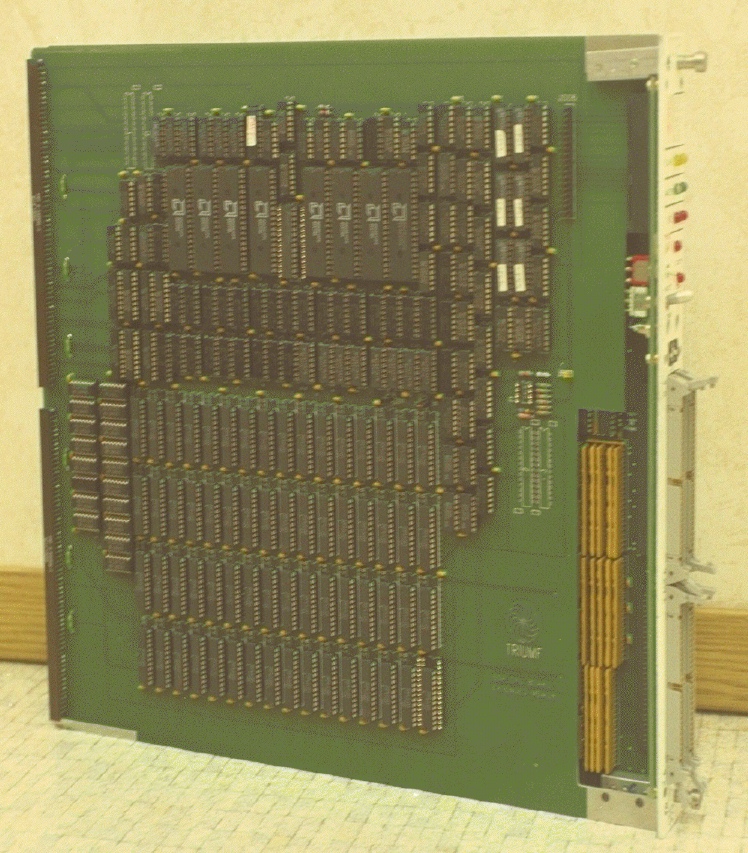 \end{rawhtml}
\subsection{Front Panel}
\begin{itemize}
\item LED's indicating: \index{LED's}
\itemsep -1.0ex
\begin{description}
\item Slave on Cable - Yellow
\item Slave on Crate - Yellow
\item Master on Cable - Green
\item Master on Crate - Green
\item \hyperref{Internal SR}{}{}{csr0_SR} (DONE) - Red \index{SR} \index{DONE}
\item \hyperref{SR}{}{}{csr0_SR} on Cable - Red
\item \hyperref{SR}{}{}{csr0_SR} on Crate - Red
\item CPU running - Red
\item \hyperref{Single step/instruction}{}{}{csr0_SCYC} mode - Red \index{Single Step}
\item \hyperref{Power Fail}{}{}{csr0_PF} - Red (optional) \index{Power Fail}
\end{description}
\item Locking toggle switch for \hyperref{Reset}{}{}{csr0_Reset} \index{Reset}
\begin{description}
\item Resets the SSP only; Puts SSP to `sleep'
\end{description}
\item Push Button for Single step/instruction
\item LEMO (NIM) input for START \index{START}
\begin{description}
\item Starts SSP
\item Similar to \hyperref{TRIGGER bit in CSR\#0}{}{}{csr0_TRIG} \index{Trigger}
\end{description}
\item LEMO (TTL open collector) output for DONE
\begin{description}
\item Same as internal \hyperref{SR}{}{}{csr0_SR}
\end{description}
\item DIPswitch to select Cable Segment Geographic Address
\end{itemize} \index{Cable Segment}
\subsection{Memory and registers}
\begin{itemize}
\item \hyperref{CSR\#0}{}{}{s_CSR0}
\begin{description}
\item Read/Write from FASTBUS or the processor
\end{description}
\item \hyperref{CSR\#8}{}{}{s_CSR8} \index{CSR\#8}
\begin{description}
\item Write only from FASTBUS
\item Arbitration level common to both Crate and Cable segment
\end{description}
\item Program memory - 4K words or 64K words,
\hyperref{switchable}{}{}{EPM}
\begin{description} \index{Program Memory}
\item Read/Write from FASTBUS
\item Addressed in CSR space
\begin{description}
\item 40000000 - 4000FFFF
\end{description}
\end{description}
\item Data memory - 512K words, \hyperref{expandable}{}{}{Jumpers} to 2048K words
\begin{description} \index{Data Memory}
\item Read/Write from FASTBUS or the processor
\item Byte addressable from the processor
\item Addressed in DATA space
\begin{description}
\item 00000000 - 007FFFFC
\end{description}
\item Addressed in CSR space
\begin{description}
\item 80000000 - 807FFFFC
\end{description}
\end{description}
\end{itemize}
\subsection{Broadcast modes}\label{s_BRO}
\begin{itemize} \index{Broadcast+}
\item Case 1 (X'01') General - SSP attaches \index{Class N}
\item Case 2 (X'N5') \hyperref{Class N}{}{}{csr0_CLASS} - N is loaded into
\hyperref{CSR\#0}{}{}{s_CSR0}
\item Case 3a (X'19') SSP asserts TP on segment issuing the
broadcast if not busy \index{Busy}
\item Case 4 (X'0D') SSP asserts TP on segment issuing the
broadcast \index{TP}
\item Case 5 (X'1D') SSP asserts TP if it is asserting
\hyperref{SR}{}{}{csr0_SR} on segment
issuing the broadcast
\item Case 6 (X'2D') SSP asserts TP if
\hyperref{DONE}{}{}{csr0_SR} (SR flag) is set
\item Case 7 (X'\{8-F\}D') User may enable by burning a
\hyperref{PROM}{}{}{BCPROM}
\end{itemize} \index{SR} \index{DONE}
\subsection{Data Cycles}
\begin{itemize}
\item Secondary Address (Read/write)
\item Random Data (Read/Write)
\item Block Transfers - Handshake (Read/Write)
\begin{description} \index{Timing}
\item Timing -- Typical for Backplane
\item Slave:
\item Primary Address: AK UP response to AS UP - 40 ns
\item Random Data : DK UP response to DS UP - 215 ns read\\
DK UP response to DS UP - 140 ns write\\
DK DN response to DK DN - 50 ns
\item Block Transfer : DK T response to DS T - 120 ns
\item Master:
\item Random Data : DS DN response to DK UP - 140 ns read\\
DS DN response to DK DN - 50 ns write
\item Block Transfer : DS T response to DK T - 110 ns
\item Maximum Transfer rate (Slave response = 0 ns):
9 Mhz (110 ns/Word). \index{Block Transfer}
\end{description}
\end{itemize}
\subsection{SS Responses}\label{s_SS}
\begin{itemize}
\item SLAVE \index{SS+}
\begin{description}
\item SS = 0, Normal
\item SS = 1, SSP is busy
\item SS = 6, Addressing error
\end{description}
\end{itemize}
\begin{itemize}
\item MASTER
\begin{description}
\item Any SS other than 0 will generate an error
except where SS=2 terminates the \hyperref{block
transfer}{}{}{BLOCK}.
\end{description}
\end{itemize}
\subsection{ Parity:}
\begin{itemize} \index{Parity}
\item No parity checking is done
\end{itemize}
\subsection{ Reset Bus:}
\begin{itemize} \index{RB+}
\item Issued by another Master:
\begin{description}
\item Resets \hyperref{CSR\#0}{}{}{s_CSR0}.
The value of \hyperref{N}{}{}{csr0_CLASS} in CSR\#0 remains unchanged.
\item Puts SSP to `sleep'.
\item Leaves all memory and other registers unchanged.
\end{description}
\item Issued by the SSP:
\begin{description}
\item Ignored by the SSP
\item Segment determined by a \hyperref{bit in
CSR\#0}{}{}{csr0_RB}
\item Level or Pulse selected by \hyperref{jumper}{}{}{Jumpers}; if level,
Duration determined by setting
and resetting a \hyperref{bit in CSR\#0}{}{}{csr0_RB}
\end{description} \index{CSR\#0}
\item Issued through the scanner
\begin{description}
\item Ignored by the SSP
\item Segment determined by a bit in \hyperref{CSR\#0}{}{}{csr0_RB}
\item Duration determined by setting
and resetting a bit in CSR\#0
\end{description}
\end{itemize}
\subsection{ START:}
\begin{itemize} \index{START}
\item \hyperref{CSR\#0 Trigger}{}{}{csr0_TRIG}
\item TTL - LEMO
\end{itemize}
Multiple starts are ignored while the processor is running
\subsection{ CPU:}
\begin{itemize}
\item 32 Bit
\item Emulates IBM integer machine language instructions.
All instructions are 32 bits long.
\item Separated Data and Program memory.
\item Executes single or combined FASTBUS I/O operations.
\item Basic cycle time of 100 ns.
Narrowed to 80 during multiply, divide, and shifts.
\item Users I/O and Error handler starts at location 0
in Program memory.
Updated \hyperref{PSW}{}{}{s_PSW} in location 0 in data memory.
\hyperref{Memory Address register}{}{}{MAR} contents in location 4
in Data memory.
\item \hyperref{Interruptible}{}{}{INTRP} from either the Crate or Cable segment
at the end of an instruction or group of I/O instructions.
\hyperref{System mask}{}{}{SMSK} must be on.
\end{itemize}
\clearpage
\subsection{ SCANNER CSR's}
The SSP has only 2 CSR's, \hyperref{CSR\#0}{}{}{s_CSR0} and
\hyperref{CSR\#8}{}{}{s_CSR8}. CSR\#0 is a read/write
register, CSR\#8 is a write only register. \index{CSR\#8+}
\subsection{ CSR\#0:} The format of CSR\#0 is shown in Table
1.\label{s_CSR0}
%\end{document}
\begin{latexonly}
\begin{center}
\begin{tabular}{|llll|}
\multicolumn{4}{c}{\large Table 1: Format of CSR\#0} \\ \hline
\bf{Bit} & \bf{Hex} & \bf{Read} & \bf{Write} \\ \hline \index{CSR\#0+}
31 & 80000000 & & Disable EPM \\
30 & 40000000 & Bits 16-31 & Reset (disable Class N) \\
29 & 20000000 & Manufacturer's & \\
28 & 10000000 & I.D. & Enable EPM\\
\hline \index{EPM} \index{Class N}
27 & 08000000 & 0106 (no EPM) & Enable Class N response \\
26 & 04000000 & & Enable Time-outs \\
25 & 02000000 & 0107 (with EPM) & Disable CI SR \\
24 & 01000000 & & Enable CI Mastership \\
\hline \index{Timeout}
23 & 00800000 & & Disable GK up \\
22 & 00400000 & & Disable single cycle \\
21 & 00200000 & & Reset SR \\
20 & 00100000 & & Disable CR SR \\
\hline \index{SR}
19 & 00080000 & & Reset RB \\
18 & 00040000 & & Reset RUN, HALT \\
17 & 00020000 & & Enable CI RB \\
16 & 00010000 & EPM enabled & Enable writing of class \\
\hline
15 & & & \\
14 & 0000X000 & Bits 12-15 & Bits 12-15 \\
13 & & Class for case 2 & Set Class for case 2 \\
12 & & Broadcasts & Broadcasts \\
\hline \index{Broadcast}
11 & 00000800 & Class N enabled & Trigger \\
10 & 00000400 & Time-outs Disabled & Disable Time-outs \\
9 & 00000200 & CI SR Enabled & Enable CI SR \\
8 & 00000100 & CR Mastership Enabled & Enable CR Mastership \\
\hline \index{GK} \index{Single Step}
7 & 00000080 & Hold GK Enabled & Enable Hold GK \\
6 & 00000040 & Single cycle mode & Set single cycle mode \\
5 & 00000020 & SR set (DONE) & Set SR \\
4 & 00000010 & CR SR Enabled & Enable CR SR \\
\hline \index{DONE} \index{Trigger}
3 & 00000008 & Cable SR is set & Set RB \\
2 & 00000004 & RUN Bit Set & Set RUN Bit \\
1 & 00000002 & Crate SR is set & Enable CR RB \\
0 & 00000001 & Power fault & Set Soft Halt \\
\hline
\end{tabular}
CR - Crate segment, CI - Cable segment
\end{center}
\end{latexonly}
\begin{htmlonly}
\index{EPM} \index{Class N}
\index{DONE} \index{Trigger}
\index{SR}
\index{Broadcast}
\index{GK} \index{Single Step}
\begin{rawhtml}
\end{rawhtml}
\subsection{Front Panel}
\begin{itemize}
\item LED's indicating: \index{LED's}
\itemsep -1.0ex
\begin{description}
\item Slave on Cable - Yellow
\item Slave on Crate - Yellow
\item Master on Cable - Green
\item Master on Crate - Green
\item \hyperref{Internal SR}{}{}{csr0_SR} (DONE) - Red \index{SR} \index{DONE}
\item \hyperref{SR}{}{}{csr0_SR} on Cable - Red
\item \hyperref{SR}{}{}{csr0_SR} on Crate - Red
\item CPU running - Red
\item \hyperref{Single step/instruction}{}{}{csr0_SCYC} mode - Red \index{Single Step}
\item \hyperref{Power Fail}{}{}{csr0_PF} - Red (optional) \index{Power Fail}
\end{description}
\item Locking toggle switch for \hyperref{Reset}{}{}{csr0_Reset} \index{Reset}
\begin{description}
\item Resets the SSP only; Puts SSP to `sleep'
\end{description}
\item Push Button for Single step/instruction
\item LEMO (NIM) input for START \index{START}
\begin{description}
\item Starts SSP
\item Similar to \hyperref{TRIGGER bit in CSR\#0}{}{}{csr0_TRIG} \index{Trigger}
\end{description}
\item LEMO (TTL open collector) output for DONE
\begin{description}
\item Same as internal \hyperref{SR}{}{}{csr0_SR}
\end{description}
\item DIPswitch to select Cable Segment Geographic Address
\end{itemize} \index{Cable Segment}
\subsection{Memory and registers}
\begin{itemize}
\item \hyperref{CSR\#0}{}{}{s_CSR0}
\begin{description}
\item Read/Write from FASTBUS or the processor
\end{description}
\item \hyperref{CSR\#8}{}{}{s_CSR8} \index{CSR\#8}
\begin{description}
\item Write only from FASTBUS
\item Arbitration level common to both Crate and Cable segment
\end{description}
\item Program memory - 4K words or 64K words,
\hyperref{switchable}{}{}{EPM}
\begin{description} \index{Program Memory}
\item Read/Write from FASTBUS
\item Addressed in CSR space
\begin{description}
\item 40000000 - 4000FFFF
\end{description}
\end{description}
\item Data memory - 512K words, \hyperref{expandable}{}{}{Jumpers} to 2048K words
\begin{description} \index{Data Memory}
\item Read/Write from FASTBUS or the processor
\item Byte addressable from the processor
\item Addressed in DATA space
\begin{description}
\item 00000000 - 007FFFFC
\end{description}
\item Addressed in CSR space
\begin{description}
\item 80000000 - 807FFFFC
\end{description}
\end{description}
\end{itemize}
\subsection{Broadcast modes}\label{s_BRO}
\begin{itemize} \index{Broadcast+}
\item Case 1 (X'01') General - SSP attaches \index{Class N}
\item Case 2 (X'N5') \hyperref{Class N}{}{}{csr0_CLASS} - N is loaded into
\hyperref{CSR\#0}{}{}{s_CSR0}
\item Case 3a (X'19') SSP asserts TP on segment issuing the
broadcast if not busy \index{Busy}
\item Case 4 (X'0D') SSP asserts TP on segment issuing the
broadcast \index{TP}
\item Case 5 (X'1D') SSP asserts TP if it is asserting
\hyperref{SR}{}{}{csr0_SR} on segment
issuing the broadcast
\item Case 6 (X'2D') SSP asserts TP if
\hyperref{DONE}{}{}{csr0_SR} (SR flag) is set
\item Case 7 (X'\{8-F\}D') User may enable by burning a
\hyperref{PROM}{}{}{BCPROM}
\end{itemize} \index{SR} \index{DONE}
\subsection{Data Cycles}
\begin{itemize}
\item Secondary Address (Read/write)
\item Random Data (Read/Write)
\item Block Transfers - Handshake (Read/Write)
\begin{description} \index{Timing}
\item Timing -- Typical for Backplane
\item Slave:
\item Primary Address: AK UP response to AS UP - 40 ns
\item Random Data : DK UP response to DS UP - 215 ns read\\
DK UP response to DS UP - 140 ns write\\
DK DN response to DK DN - 50 ns
\item Block Transfer : DK T response to DS T - 120 ns
\item Master:
\item Random Data : DS DN response to DK UP - 140 ns read\\
DS DN response to DK DN - 50 ns write
\item Block Transfer : DS T response to DK T - 110 ns
\item Maximum Transfer rate (Slave response = 0 ns):
9 Mhz (110 ns/Word). \index{Block Transfer}
\end{description}
\end{itemize}
\subsection{SS Responses}\label{s_SS}
\begin{itemize}
\item SLAVE \index{SS+}
\begin{description}
\item SS = 0, Normal
\item SS = 1, SSP is busy
\item SS = 6, Addressing error
\end{description}
\end{itemize}
\begin{itemize}
\item MASTER
\begin{description}
\item Any SS other than 0 will generate an error
except where SS=2 terminates the \hyperref{block
transfer}{}{}{BLOCK}.
\end{description}
\end{itemize}
\subsection{ Parity:}
\begin{itemize} \index{Parity}
\item No parity checking is done
\end{itemize}
\subsection{ Reset Bus:}
\begin{itemize} \index{RB+}
\item Issued by another Master:
\begin{description}
\item Resets \hyperref{CSR\#0}{}{}{s_CSR0}.
The value of \hyperref{N}{}{}{csr0_CLASS} in CSR\#0 remains unchanged.
\item Puts SSP to `sleep'.
\item Leaves all memory and other registers unchanged.
\end{description}
\item Issued by the SSP:
\begin{description}
\item Ignored by the SSP
\item Segment determined by a \hyperref{bit in
CSR\#0}{}{}{csr0_RB}
\item Level or Pulse selected by \hyperref{jumper}{}{}{Jumpers}; if level,
Duration determined by setting
and resetting a \hyperref{bit in CSR\#0}{}{}{csr0_RB}
\end{description} \index{CSR\#0}
\item Issued through the scanner
\begin{description}
\item Ignored by the SSP
\item Segment determined by a bit in \hyperref{CSR\#0}{}{}{csr0_RB}
\item Duration determined by setting
and resetting a bit in CSR\#0
\end{description}
\end{itemize}
\subsection{ START:}
\begin{itemize} \index{START}
\item \hyperref{CSR\#0 Trigger}{}{}{csr0_TRIG}
\item TTL - LEMO
\end{itemize}
Multiple starts are ignored while the processor is running
\subsection{ CPU:}
\begin{itemize}
\item 32 Bit
\item Emulates IBM integer machine language instructions.
All instructions are 32 bits long.
\item Separated Data and Program memory.
\item Executes single or combined FASTBUS I/O operations.
\item Basic cycle time of 100 ns.
Narrowed to 80 during multiply, divide, and shifts.
\item Users I/O and Error handler starts at location 0
in Program memory.
Updated \hyperref{PSW}{}{}{s_PSW} in location 0 in data memory.
\hyperref{Memory Address register}{}{}{MAR} contents in location 4
in Data memory.
\item \hyperref{Interruptible}{}{}{INTRP} from either the Crate or Cable segment
at the end of an instruction or group of I/O instructions.
\hyperref{System mask}{}{}{SMSK} must be on.
\end{itemize}
\clearpage
\subsection{ SCANNER CSR's}
The SSP has only 2 CSR's, \hyperref{CSR\#0}{}{}{s_CSR0} and
\hyperref{CSR\#8}{}{}{s_CSR8}. CSR\#0 is a read/write
register, CSR\#8 is a write only register. \index{CSR\#8+}
\subsection{ CSR\#0:} The format of CSR\#0 is shown in Table
1.\label{s_CSR0}
%\end{document}
\begin{latexonly}
\begin{center}
\begin{tabular}{|llll|}
\multicolumn{4}{c}{\large Table 1: Format of CSR\#0} \\ \hline
\bf{Bit} & \bf{Hex} & \bf{Read} & \bf{Write} \\ \hline \index{CSR\#0+}
31 & 80000000 & & Disable EPM \\
30 & 40000000 & Bits 16-31 & Reset (disable Class N) \\
29 & 20000000 & Manufacturer's & \\
28 & 10000000 & I.D. & Enable EPM\\
\hline \index{EPM} \index{Class N}
27 & 08000000 & 0106 (no EPM) & Enable Class N response \\
26 & 04000000 & & Enable Time-outs \\
25 & 02000000 & 0107 (with EPM) & Disable CI SR \\
24 & 01000000 & & Enable CI Mastership \\
\hline \index{Timeout}
23 & 00800000 & & Disable GK up \\
22 & 00400000 & & Disable single cycle \\
21 & 00200000 & & Reset SR \\
20 & 00100000 & & Disable CR SR \\
\hline \index{SR}
19 & 00080000 & & Reset RB \\
18 & 00040000 & & Reset RUN, HALT \\
17 & 00020000 & & Enable CI RB \\
16 & 00010000 & EPM enabled & Enable writing of class \\
\hline
15 & & & \\
14 & 0000X000 & Bits 12-15 & Bits 12-15 \\
13 & & Class for case 2 & Set Class for case 2 \\
12 & & Broadcasts & Broadcasts \\
\hline \index{Broadcast}
11 & 00000800 & Class N enabled & Trigger \\
10 & 00000400 & Time-outs Disabled & Disable Time-outs \\
9 & 00000200 & CI SR Enabled & Enable CI SR \\
8 & 00000100 & CR Mastership Enabled & Enable CR Mastership \\
\hline \index{GK} \index{Single Step}
7 & 00000080 & Hold GK Enabled & Enable Hold GK \\
6 & 00000040 & Single cycle mode & Set single cycle mode \\
5 & 00000020 & SR set (DONE) & Set SR \\
4 & 00000010 & CR SR Enabled & Enable CR SR \\
\hline \index{DONE} \index{Trigger}
3 & 00000008 & Cable SR is set & Set RB \\
2 & 00000004 & RUN Bit Set & Set RUN Bit \\
1 & 00000002 & Crate SR is set & Enable CR RB \\
0 & 00000001 & Power fault & Set Soft Halt \\
\hline
\end{tabular}
CR - Crate segment, CI - Cable segment
\end{center}
\end{latexonly}
\begin{htmlonly}
\index{EPM} \index{Class N}
\index{DONE} \index{Trigger}
\index{SR}
\index{Broadcast}
\index{GK} \index{Single Step}
\begin{rawhtml}