


Next: 6 PCL ELECTRICAL CHARACTERISTICS
Up: No Title
Previous: 4.9 MASTER INTERFACE SIGNALS
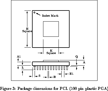
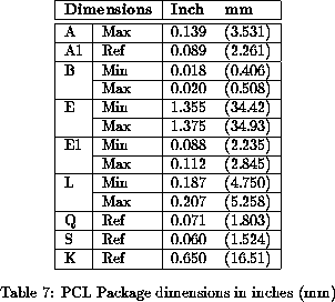
Physical Dimensions The PCL is packaged in a 100-pin plastic pin-grid array (PGA). The dimensions
are shown in Figure 3 (page
The PCL is packaged in a 100-pin plastic pin-grid array (PGA). The dimensions
are shown in Figure 3 (page  ) and
Table 7 (page ).
) and
Table 7 (page ).
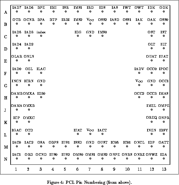
The pinout is shown in Figure 4 (page ). The PCL
pins are specified using a grid system; eg. output signal OEL is on pin F2.
Next: 6 PCL ELECTRICAL CHARACTERISTICS
Up: No Title
Previous: 4.9 MASTER INTERFACE SIGNALS